Since my previous posts about stand mixers and food processors, it seems like kitchen appliances is becoming my “thing”. I saw a Wilfa Svart coffee grinder being given away on a local share group. It wasn’t working and the owner had correctly identified that the cause of the fault was a failed capacitor, as documented in this post on coffee forums, but didn’t have the time or equipment to repair it, so instead gave it away. I’d already been thinking about getting a coffee grinder so I jumped on the opportunity. These units are popular for good reason – they seem to be well made (apart from the electronics) and the simple interface allows you to turn the bean hopper to set the grind coarseness, turn the knob to set the time to grind (so amount of coffee), and press the button to receive coffee.
As per the prediction, the issue seemed to just be the one capacitor and once I exchanged it, the grinder worked again.
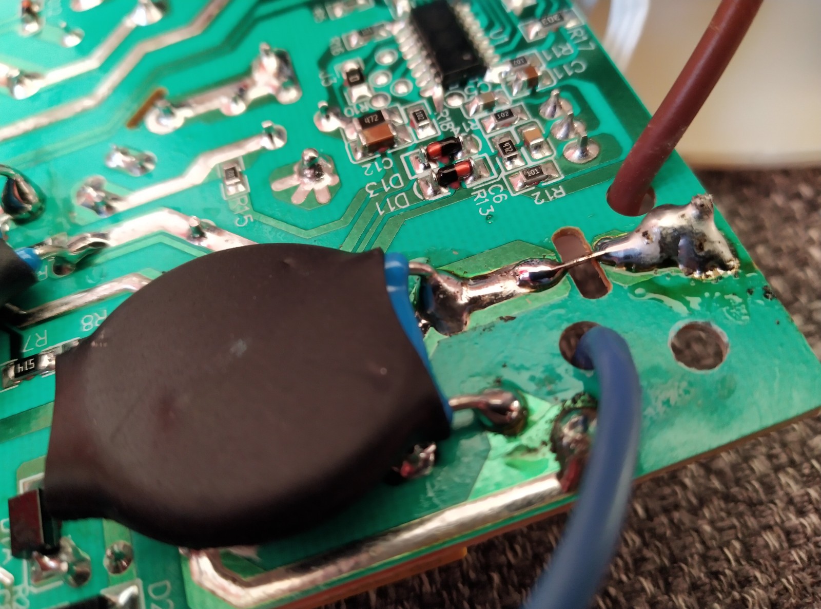
I unfortunately made a big mess in doing so, damaging the FR2 PCB and some components and having to repair it with wire mods. Optimistic that I’d never need to open it again, I gunked it up with some silicone to hide my sins.
All was well for a while, and I also got lucky and found 6 more grinders in the trash outside my office.
Three of these seemed to have the same fault as the first one I got: making strange noises or stopping prematurely. Another one seemed to grind constantly when power was applied and another two seemed to work fine. At about the same time, the first one I modified was starting to play up – making strange noises again like with the capacitor fault. This got me curious about the circuitry so I set about reverse engineering it.
This schematic isn’t very readable but in reverse engineering it I discovered two interesting things:
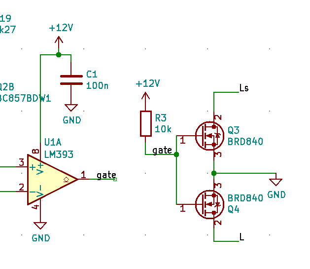
The DC motor is, strangely, powered through a bridge rectifier switched by a TRIAC. It seems like a strange choice to switch a DC motor using a DC signal, but use a TRIAC on the AC side. I’d have expected a MOSFET to be used instead. Perhaps this was done for cost reasons?
The digital circuitry is supplied through a capacitive dropper – the capacitor which is known to fail.
The latter seemed like a poor design choice to me. It’s very common to see safety capacitors used in a capacitive dropper like this, but it isn’t generally a recommended use for these types. Vishay have an application note on the various uses for safety capacitors, with a specific recommendation for a range which is suitable for use in series with the mains like this – illustrating that not all such capacitors are suitable for this application. I’m not entirely sure of the reason for their unsuitability but I suspect it’s related to their self-healing, which depends on enough current being available to burn through the metallisation and contain short circuits when the dielectric fails.
I put together a design for a complete replacement for the electronics in KiCAD. To summarise the key design decisions:
The input protection, consisting of a fuse, MOV and a safety capacitor are copied directly from the original. I’m not an expert in electrical safety and nor do I have the equipment to test emissions so I decided not to touch this. I figured nothing else I was changing would have any significant effect on these.
The timing is done by an MC14541BD. The capacitor is chosen to give the same maximum time (30s) as the original, with a minimum of around 1 second.
The potentiometer is reused from the original. Apart from this, the circuit uses all new electronic components with nothing being scavenged from the original. But I wasn’t able to find a potentiometer with the same mounting hardware. If anyone else fancies having a go, the original is around 47-50kohm.
The timing circuit has a power-on reset. When the button is pressed, the MC14541BD powers up and produces one pulse. While the output is high, the motor is switched on with a MOSFET. Another pair of MOSFETs bypass the switch to continue to provide power to the timer.
The DC power supply is produced using an LR8 regulator: a linear regulator suitable for input voltages up to 450V. It has a minimum load of 500uA to maintain regulation, and the potential divider I chose consumes 600uA. This makes up all of the standby power consumption of the device: around 600uA at 300VDC, or around 0.18W, which corresponds to about 1.5kWh per year.
Electrolytic capacitors can be the limiting factor in a circuit’s lifetime, so where I had to use one, I used a rubycon one rather than an unknown brand
I measured up the original PCB, including the location of the potentiometer and tactile switch, and made a very quick and dirty layout. I noticed that the original PCB seemed to have a copper keepout at the bottom and top of the PCB. I assumed this was related so some kind of safety/double insulation requirement so kept this the same in mine.
Here is the circuit soldered up, except for the potentiometer and interlock switches which are bypassed for testing. The quality of the soldering betrays the fact that I’m a design engineer and not an assembly technician but luckily this caused no problems. On the first test I could see that there was one issue though: when the button is pressed the circuit switches on, but it never switches off again. If I watched closely, I could see the motor LED flash off briefly about once per second.
I connected up just the low voltage side to a bench power supply and saw the problem: the power-on reset of the MC14541BD also triggers on power off.
Here, yellow shows the power supply pin of the MC14541BD and the green shows the output. When the timer runs out, the output immediately goes low, which switches off the MOSFET providing power. After a few hundred microseconds, the power supply rail falls. When it reaches around 4-5V, the power-on reset triggers, resets the timer and switches the MOSFET back on. It gets stuck in this loop which it can never leave. To me, this is incorrect behaviour of a power-on reset: it should have a hysteresis and only trigger on a rising edge of the supply voltage. Nonetheless I found a solution.
I replaced the series resistor with a 6V8 zener: this gives enough voltage on the gate to switch on the MOSFETs when the supply is fully up, but prevents it from activating the MOSFET when the supply is low. Here the yellow trace again shows the power supply, but the green line shows the MOSFET Vgs. You can see that, as before, the IC tried to switch the MOSFET again, but isn’t able to reach the threshold voltage because of the zener. In fact, I improved this further by changing the pull-down resistor from 1M to 10k. After this, there was no visible change in the gate voltage when the timer resets.
And with that, we have a working coffee grinder! I added the zener and replace the resistor on the 10 boards I got made:
And even got my partner to replace the board in one of the broken grinders:
All that remains is to do a bit of a clean-up. When I found these 6 grinders in the trash, I asked around several of my friends to see if they wanted one. Most of them said that they already had this exact model of grinder! It’s clearly a popular model so I figured some folk reading this might want to follow in my footsteps – in which case it makes sense for me to do the small updates which are needed for the design. The changes were:
The zener diode modification described above
It turned out that the motor wires were a bit thicker than the 2.5mm holes I used, so I expanded these to 3.5mm
The 2012 capacitor on the output of the LR8 regulator was a bit tricky to hand solder. I changed the footprint to one with larger pads for hand soldering
The push button footprint was a bit too narrow. I widened the pads a little
Moved the LR8 up a little to give more room for soldering
Increased the LR8 output voltage a little and increased the zener voltage to 9V1 to give a bit more margin against the unknown variation in the timer’s power-on-reset threshold without affecting the gate voltage on the MOSFETs in normal operation
And here are the kicad design file and gerbers. The gerbers are ready to be uploaded to JLCPCB, and you can add assembly of the bottom side with a little bit of manual placement.
Let me know if this is useful to you! Comment on here or send me an email on alec@nothinguntoward.eu. Since I know a few people who use this grinder, I might get a few more of these PCBs made, so if you’re lucky and you email me, I might be able to spare one. Good luck to anyone else following along at home!
I recently got hold of this retro looking instrument lamp as a freebie from a local share group:
It’s a little bit tatty and the dimmer didn’t work but I thought it seemed like a great opportunity for a project. Opening it up, I found that the dimmer was actually just a wirewound variable resistor. It seemed like there was a break in the resistance wire somewhere, which would explain why the lamp wouldn’t work.
I had a think about what to do with this project. I decided that I’d like to change it to use LEDs, and create a new dimmer. But what kind of LEDs? Something on my todo list for someday is to actually design my own LED board, so I know I’m using emitters with high CRI and the thermal management is good. But I decided that that wasn’t a task for this project, and using a filament LED bulb would give it more character, and be less custom circuitry to maintain and debug.
Dimming
The problem with using an off-the-shelf LED bulb is the dimming: if you’ve ever tried using a supposedly “dimmable” LED bulb with a conventional TRIAC dimmer, you’ll know that the results can be hit-and-miss. As far as I’m aware, the main reason for this is that the current consumption of an LED bulb is typically below the hold current of a TRIAC. Take the BT137 for example. It has a typical hold current of 2.5mA, which corresponds to 0.6W at 230V. But it could be as high as 20mA, corresponding to about 5W. With a load smaller than the hold current, the TRIAC will switch off, only to be triggered again once sufficient voltage develops across the gate circuitry. And this will result in the all-too-familiar annoying buzzing, and probably flickering too. So for LEDs, TRIAC dimmers are out.
But why trailing edge?
That explains why we can’t use a TRIAC as the switching element of a phase-control dimmer. But why is it commonly said that trailing edge dimmers are preferred over leading edge for LEDs?
To be honest, I’m not entirely sure. I suspect this is a comparatively minor optimisation. A reason I’ve heard alluded to but not explicitly discussed in any detail is that the sharp leading edge can cause some unspecified problems. I’m not sure if this is current stresses affecting reliability, or high dI/dt causing audible noise in magnetic components. I’d hazard a guess that step one in development of LED dimmers was that TRIACs were abandoned in favour of back to back MOSFETs, and so more complex control circuitry (probably microcontroller based) was required. And once you’re using a microcontroller anyway, you may as well use trailing edge dimming to avoid the current spike on the leading edge too!
One other possibility I considered was, since most LED bulbs will have rectification and smoothing, does trailing edge dimming give finer control over average rectified voltage? The answer is, not really. The animations below show a simulation of a leading-edge and trailing-edge dimmed signal, a full-wave rectified DC voltage produced from that, and the average voltage.
In both cases, the average DC voltage essentially just follows the peak of the waveform, and so the DC voltage increases in a comparable way. The variation in average DC voltage with phase angle is plotted here:
As you’d expect, after 90 degrees there’s essentially no further increase, as the peak of the AC waveform is already being rectified. There’s a very slight variation due to a small difference in droop between the two cases.
That’s as much as I’m going to say on the motivation behind trailing edge dimmers, but if you want to see some practical examples, John Ward has a demonstration of a few on his youtube channel.
Implementation
Having decided to use a trailing edge dimmer, the next question was how to do it. The obvious option is to just buy or adapt something off-the shelf. Since the dimmer unit on the lamp is slightly larger than a standard pattress box, it should be possible to adapt a standard wall-mounting dimmer switch. This would probably have been the cheapest and easiest solution, but off-the-shelf dimmer switches still aren’t cheap enough to put me off having some fun by designing my own.
As far as designing my own is concerned, there seem to be three options: the easiest is to use a dimmer IC, such as Fairchild’s FL5150. It seems like a nice integrated solution and GreatScott! did a PCB layout using it. The second option would be to make a microcontroller circuit: essentially digitising a potentiometer input, synchronising to the mains switching and producing a pulse to turn on the back-to-back MOSFETs. Again, in the same video above, GreatScott! does exactly that. I didn’t choose either of these options though. The FL5150 wasn’t in stock on LCSC and I couldn’t be bothered to look elsewhere. I didn’t want to use a microcontroller because there’s pretty much nothing I enjoy about working with microcontrollers: installing development environments, finding where I put my programmer, writing and debugging code, fixing problems with device or programmer detection. All of these things make me want to cry and I’d rather be doing some analog electronic design.
So that’s what I decided to do: create a dimmer circuit in analog electronics. I figured this would nicely complement the two approaches GreatScott! had already explored too.
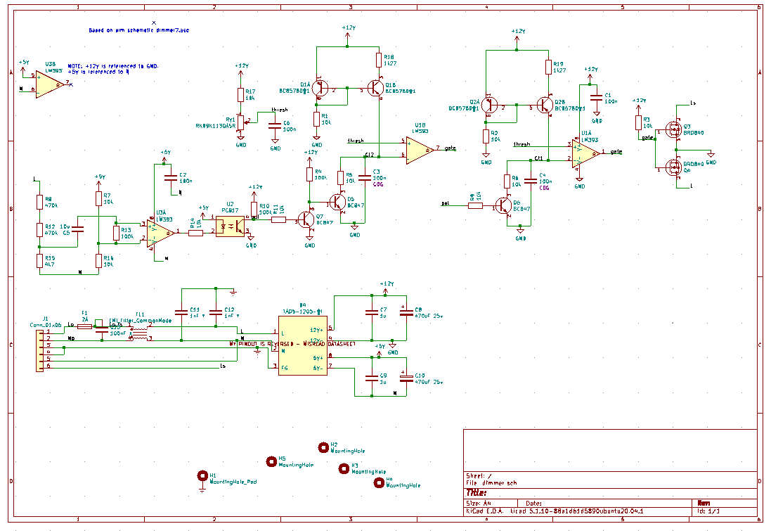
Circuit Block Diagram
The general idea for this circuit is that the light bulb current will be switched on or off by two back-to-back MOSFETs to give bidirectional current control. These will be driven by a pulse generator with a potentiometer to provide the setpoint, and that will rely on a zero-crossing detector for the mains voltage.
The frustrating thing is, I couldn’t think of a way to implement this without an optoisolator in the middle. The pulse generator circuit needs to produce an output referenced to the common source of the MOSFETs. However, such a circuit wouldn’t be able to see every mains voltage transition, since it can only see the mains voltage when one or other of the MOSFETs is switched on (which won’t be the case at a transition, except at 100% output), or a body diode is forward biased. And if we rely on this, depending on which body diode we’re using we might see the (unknown) voltage drop across the load in addition to the forward voltage. The FL5150 IC seems to achieve this, unless it’s secretly using some kind of capacitive isolator, but I couldn’t figure out how so I’m stuck with the optoisolator.
Zero-Crossing Detector
The simplest way to achieve the zero-crossing detection would have just been to place the optocoupler across the supply either to detect its polarity or, as GreatScott! did, use an optoisolator with reverse-parallel emitters to produce a “blip” at a zero-crossing. The problem with this is that there’s a tradeoff between the phase accuracy and power dissipation – and a hard limit on the latter imposed by the optocoupler.
Here, he’s chosen 100kohm of series resistance. That gives a maximum current of around 3.3mA with 230VAC. But the current transfer ratio is around 100%, meaning that, assuming a 10kohm pullup inside the ATTiny and a ~2.5V threshold, about 250uA needs to flow to cause a transition, which corresponds to a voltage of around 25V across the mains supply. So the transition will happen typically ~25V either side of the threshold. This will give a phase error of typically about asin(25*sqrt(2)/230)=9 degrees, which isn’t good enough for my liking! If the optocoupler transfer ratio is at its minimum of 50%, the phase error will be even worse. Plus, this circuit is burning around about 230V*230V/100k = 0.5W, which is rather a lot of energy to waste when we’ll only be dimming a <10W bulb!
My choice of circuit uses a comparator to give a precise transition. An LM393 clone is used simply because it was the cheapest dual comparator on LCSC and I need a dual comparator later on. The RC network on the input biases the comparator inputs within the common mode range of the comparator, and then detects the polarity of the AC component. It should be obvious that both comparator inputs will see the same DC component (give or take input bias currents*100kohm) – simply ignore anything left of the capacitor since no DC current will flow through here. So both comparator inputs will be biased at 2.5V.
For the AC component, we can treat C5 as a short circuit since the impedance at 50Hz is just 318 ohms. This gives a thévenin equivalent circuit thus:
From this we can see that the majority of the 1.62V peak AC will be seen across the comparator input. The comparator is specified to have an input offset voltage of +/-5mV max, and is specified to have a negligible (~1us) switching time with 5mV overdrive, so it should trigger within arcsin(10mV/1.62V) = 0.35 degrees of the line transition. Another source of error is the phase shift of the RC network. Bringing the 318 ohms impedance of the capacitor back in, this will mean the impedance of this circuit is at an angle of atan(0.318k/(100k+5k+4.68k))=0.16 degrees. So in total, this circuit indicates the phase of the AC line signal with about 0.51 degrees of phase error.
The more pedantic might point out that this isn’t really a zero-crossing detector: just a polarity detector!
Pulse Generator
After the optoisolator (just selected as the cheapest one available on LCSC!), we need a pulse generator. This needs to produce a pulse on each change of AC signal polarity, of a duration set by the position of a potentiometer. For this, I’ll charge a capacitor at each transition and turn off the MOSFET when we reach the threshold set by the potentiometer. I figured I’ll use two circuits like this, operating out of phase:
Timing Capacitor
In this circuit, we don’t want to use currents which are too low, otherwise leakages become an issue. But we also want to keep the capacitance low enough to allow us to use a precision type.
The circuit is going to be running off 12V (for reasons I’ll explain later), and I want the capacitor to charge up to half the supply voltage (to keep within the common mode range of the comparator) within half a mains cycle. With our mains frequency of 50Hz, this means that dV/dt=6V*50Hz*2=600V/s. Since dV/dt=I/C, this gives us the relationship between the current setpoint and the capacitance. I selected 100nF and 60uA. 60uA is low enough that the leakage of most components isn’t significant, while 100nF is the largest value I could get in 1206 C0G (a class 1 dielectric).
I could have stretched to far higher capacitances with an X7R capacitor but let’s look at the specs for, say, an AVX 10uF 25V 1206 capacitor:
The capacitance of class 2 capacitors (such as X7R) falls as voltage is applied, meaning that the charging curve at a constant current won’t be linear, initially charging slowly then faster as the voltage increases. In addition to this, temperature has a significant effect on the capacitance.
As far as I’m aware, electrolytics and tantalum capacitors don’t have a significant variation of capacitance with applied voltage, but their wide tolerances and high leakages tend to make them only really suitable for decoupling.
Current Source
One of the most interesting parts of this project was designing the current source.
Basic Current Mirror
The first option I considered was a simple current mirror, with the reference provided by the fixed 12V supply across a resistor. Here, I resorted to simulation to help with the design.
This works OK but you can see that the current mirror has an output impedance which is fairly significantly affecting the setpoint: around about 1Mohm. This gives a slightly nonlinear charging curve. The reason for this is the Early Effect, which essentially looks like a collector-emitter parallel impedance, sometimes referred to as hoe, ho or ro in the hybrid model.
Annoyingly, of the hybrid model parameters, the only one commonly specified in datasheets is hfe. I’ve never seen a datasheet which specifies Early voltage (which could be used to calculate hoe) and the datasheets for BC857 don’t even have the relevant curve to estimate it. The 1Mohm @ 60uA from the simulation though seems to suggest a ~60V Early voltage.
Widlar Mirror
The type of current source which I ended up choosing was the Widlar current source, although in hindsight this probably isn’t the best option.
The Widlar source augments the simple current mirror by adding an emitter degeneration resistor to the output transistor: this reduces the output current proportionally to exp(R1*Iout/vt) but also introduces some negative feedback to reduce the influence of the Early effect: as the output current reduces due to the Early effect, so the voltage across R1 will decrease, resulting in an increased base-emitter voltage, pushing the current back up. I’ve struggled to quantify this analytically despite this excellent article from analog (see section 11.8.2) but from this simulation, the impedance seems to have been increased to around 3.3Mohm:
One big weakness of this circuit is that there’s a significant effect of temperature on the current setpoint. The emitter degeneration resistor was selected based on a Vt of 25.8mV, which occurs at ~room temperature. As the temperature varies, the setpoint will vary. Let’s quantify this.
Temperature Variation
I first attempted to do this analytically, and found an interesting general result for Widlar current sources.
Referring to the schematic above, Vbe (=Vce) of Q2 will be given by:
The exponential is the dominating term so to make the maths easier going forward, let’s ignore the -1 in the ebers-moll equation. Q1 is going to see a Vbe reduced by the voltage across R1:
Substituting one into the other and taking beta>>1 gives:
This is the result we quoted without derivation in the previous paragraph.
And differentiating wrt temperature, with the assumption that the R4 current is independent of temperature:
Factoring out the exponential:
Rearranging for dIo/dT gives the expression:
Plugging in the numbers gives dIo/dT = 225nA/K at 300K, or 0.4% per kelvin – not great but probably tolerable given the circuit will be working indoors and there’ll be little self-heating.
There’s one further incisive observation we can make of this expression. Provided the voltage across R1 is much greater than the thermal voltage (which will typically be the case for Widlar current source), this simplifies further to just Io/T. So a proportional variation in temperature of 1/T (so about 0.3% per Kelvin) is inherent in the design of a Widlar mirror. It seems odd then that it was used in integrated circuits, since I wouldn’t expect this to be acceptable.
Iterative Analysis
I also tried an iterative method to find the effect of temperature on output current, based on the method described on Wikipedia but assuming beta tends to infinity. I set up a spreadsheet to do a few levels of iteration, then compared the output current for 1K either side of 300K. This gave me a slightly different dIo/dT of around 149nA/K. I’m not quite sure what the source of the discrepancy is here, but I’m glad the numbers came out reasonably close.
Improved Mirror
An option I hadn’t considered until doing this write-up now, and which I wish I’d used, is this improved mirror circuit, which I can’t find a name for:
The “stilts” it’s standing on have the same effect on output impedance as in the Widlar source: as more current is drawn from Q1, the voltage drop across R1 increases, bringing the current back down.
Simulation indicates an output impedance of around 33Mohm.
It’s clear also from looking at this circuit that it won’t be significantly affected by temperature, since there should be no differential in Vbe between the two transistors. But how closely do we need to match R1 and R2? How sensitive is the circuit to the difference in the two? We would expect the gain to change as R1 and R2 vary.
Let’s assume nothing changes on the left hand side of the circuit and hfe tends to infinity. That means that the base voltage (relative to the positive supply) is fixed. I’ll call that VB. So the output current is given by:
Differentiating this and substituting Io back in to cancel out the scale current and beta gives:
Rearranging gives:
We could just plug numbers in now but we can make a useful observation if we look at the right hand side of the denominator. It has two parts: , which is the ratio of the voltage across R1 to the thermal voltage, and , which is the ratio of Vbe to the thermal voltage. Both will be significantly greater than 1, and their product even more so. Thus we can ignore the 1 in the denominator and so the equation simplifies down to:
So, for as long as the assumption of R1 voltage being much greater than the thermal voltage applies, the output current just varies in proportion with the conductance of R1. This is unlike in the Widlar current source, where a change in resistance causes an exponential change in output current, giving the circuit high sensitivity to the value. This property of the improved current mirror would allow us to create a mirror with different ratios, with very little sensitivity to semiconductor parameters.
Wilkinson Mirror
A final type of current source which I won’t go into any detail here but which would also probably be an excellent choice for this circuit is the Wilkinson mirror – essentially the basic mirror but with a common-base amplifier to reduce the voltage variation seen by the mirror. Again, it’s described in this excellent source from Analog Devices.
Pulse Generator Circuit
Putting that all together, this is the pulse generator circuit:
Note that there’s no physical AND gate: since the comparators have open-drain outputs, tying them together with a pull-up resistor creates a wire-AND.
MOSFET Driving
Compared to other parts of the circuit, the MOSFET driving is relatively simple. What do we need in terms of switching time? To limit power dissipation, switching on fast is less important than switching off fast, since it will only be turning on near a transition when Vds will be low, whereas we might be turning off at any point in the mains cycle. Because of this, using the open-collector driver of the comparator and a pull-up is ideal. I chose 10k pull-up. Since the gate threshold voltage could be up to 4V, I’ve selected 12V as the power supply. This leaves 8V across the resistor. The pair of MOSFETs probably take around 200nC to switch (based on the datasheet for the similar IRF840), which means the switching time should be around 250us. Assuming (because we’re at a zero-crossing), drain voltage will be no more than 20V during a switch, and that the load will be up to 100mA, gives a turn-on dissipation of
The SN393T will pull down with a minimum of 6mA (like the LM393 which it imitates), so with a drain voltage now potentially as high as 325V, the turn-off dissipation is given by
This total dynamic dissipation of under 80mW (plus pretty negligible I²R losses) is low enough that I’m not even going to consider thermal management.
Power Supply
Earlier on in this project, I thought I might be able to get away with using under ~ a milliamp and so power the circuit with just a linear dropper from mains voltage. It turns out though, the total power consumption is a bit higher than that.
Item
Current
Source
Comparators
4mA
Datasheet max x2 parts
Current sources
2.4mA
12V/10k * 2
Gate drive
1.2mA
12V/10k
Misc resistors
1mA
Threshold circuits, inverters
Total
8.85mA
To produce the 8.85mA directly from 230V, I’d be dissipating at least 2W continuously. This isn’t acceptable for a dimmer. Instead, I decided to use this AC-DC power brick, which claims a no-load power consumption of <150mW.
It also has two outputs, isolated from one another.
I implemented it pretty much exactly as shown in the datasheet, including the EMI circuitry. While the FCC aren’t going to come hunting me down, I figured I probably ought to anyway!
Alternative Power Supplies
Before I realised the only sane option was a switched-mode power supply, I did a few experiments with other forms of power supply. Although I didn’t end up using any of the ideas I thought they might be worth sharing.
Zener Regulator
One of the simplest power supplies is just a rectifier and resistor to drop the voltage down from the mains supply, a zener to limit the voltage, and a capacitor to smooth it out. There are all kinds of problems with this: firstly, it’s no good here because unless we use a huge capacitor, there’ll be a lot of ripple – and none of the analog circuitry will thank us for that. The zener diode doesn’t regulate the voltage but rather clamps it, so the supply voltage will reach the zener voltage once per cycle, then droop.
The other problem is that these circuits are inherently power hungry: take the datasheet for BZX84C for example. For the <=24V parts, the test voltage is 5mA, which means you need at least 5mA through the diode to reach the zener voltage. Since that’s coming linearly from 230VAC, that’s 1.2W you’re burning just for the zener! As I understand it, this is one of the better zeners too.
You can get around this to some extent by using a shunt voltage regulator instead, such as TL432. This will work down to ~100uA and I’m working on another project at the moment which uses it. I’m starting to think that zener diodes are long overdue relegation to the history books – I’m struggling to think of any application where I’d choose one over a shunt regulator.
Another improvement you often see to this arrangement is replacing the resistor with a capacitor to improve efficiency: on one half of the mains cycle, the capacitor drops voltage by charging up, rather than burning power as a resistor would. On the other half of the cycle, the energy gets fed back into the mains supply. This is typically done in combination with a bridge rectifier but in this instance we might get away with just adding an antiparallel diode to discharge it:
What’s marked as live here would actually be neutral in my circuit!
I haven’t looked into this in any great detail though and I’m not sure how exactly I’d model it/select the capacitor value. I’m also not sure how much you can gain from this, given that some resistance will be needed in series to limit the peak currents.
Linear Regulator
Linear regulators are typically limited to lower voltages, but there are a few linear regulators designed to work off mains voltage directly. One example is Microchip’s LR8, which can withstand input voltages of up to 450V. This is probably one of the best solutions for loads of ~2mA or less, but less suitable for this application. Again, this is something I’m looking into for another project so I’ll be writing some more detail on this in my (hopefully!) next post.
Completed Schematic and PCB Layout
Putting together my power supply, polarity detector, pulse generator and MOSFET, the schematic is complete.
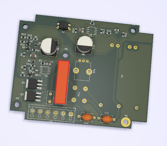
The PCB layout wasn’t too challenging, with the board having plenty of space:
Once the PCBs arrived and I started populating them: I ran into two problems. One was my fault and one was JLCPCB’s!
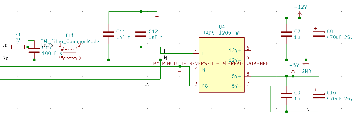
Firstly, I misread the datasheet for the AC-DC module. I’d misread the orientation of one of the drawings and my PCB footprint for the part was mirrored. I ended up having to mount it on the opposite side of the board : it’s lucky I didn’t have any tall components there!
The second problem was with the PCB manufacture. I was having problems with one of the current mirrors which I eventually narrowed down to one of the emitters of Q1 not being connected to +12V. I had to wiremod it to get the board to work!
It’s hard to see because of the silkscreen, even with a microscope, but the track/thermal which should connect the pad is completely missing.
In the gerber I sent them, it was definitely connected:
Test
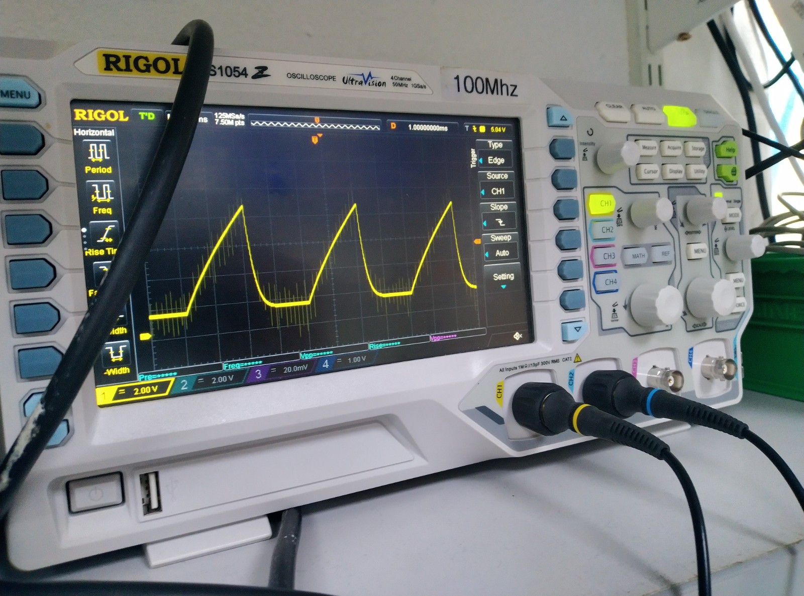
The pulse generators produce a ramp very much as you’d expect:
The charging curve isn’t as linear as I’d hoped, and the discharge is slower than I’d have liked. In hindsight, the discharge problem was due to a stupid decision on my part: I’m not sure why I chose 10k resistors, when 60uA*10k =600mV. It also gives a time constant of 1ms, which is a long time when the whole ramp is 10ms! I reduced the resistors to 1k, which seemed to improve it – I forgot to record a scope trace though!
Why is the ramp so nonlinear? It looks almost as if I oughtn’t have bothered with the current mirror at all. It looks like there’s some kind of parallel resistance. The comparator input bias current is very low so it shouldn’t be this. I considered that it might be flux on the PCB, but that’s typically in the megaohms, which shouldn’t be a problem here.
Despite this, the phase control seemed to work great:
The maximum phase is a bit off though because of the problems with the ramp generator, but in principle it seems to be working as expected.
Connecting this up to a lamp, I was a bit disappointed to find that the output was very flickery. Because of the rolling shutter/aliasing, the video makes it seem far worse than it does in real life. But it’s still not ideal. Even with an incandescent bulb, there’s a noticeable flicker.
I’m tempted to put this down to variation between the two pulse generators: since one works the positive half-cycle and the other works the negative half-cycle, any discrepancy between the two will cause a 50Hz flicker. And there are plenty of potential sources of discrepancy: the capacitors, while stable, are +/-5% starting tolerance. The emitter degeneration resistor in the current sources, to which the output current is superlinearly sensitive, are +/-1%. The circuit is also sensitive to the saturation voltage of the discharge transistors.
Conclusion
I think I’m going to conclude this project here and find some alternative solution for my lamp. A dimmer was a cool idea but maybe I don’t need one at all and a rotary switch will do?
It was interesting to dig a bit into the design and analysis of current sources, but I think I underestimated some of the subtleties of this project. If anything, it’s driven home the importance of doing tolerance analyses.
I hope this has made for interesting reading, and I welcome any comments, especially if you have any ideas what’s up with the nonlinearity of my ramp generator!
I seem to have been posting a lot about kitchen equipment lately. In this post I want to examine what seems like an odd design decision in KitchenAid’s 1.7l food processor and how I fixed it, an give a few thoughts on this piece of equipment.
The Fuse
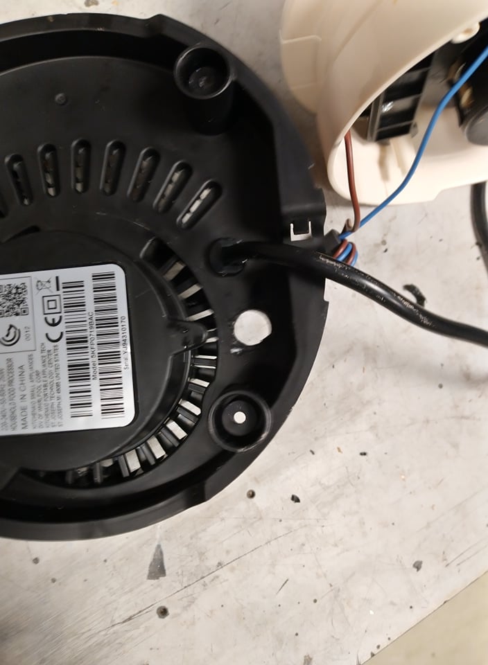
I stupidly decided to try and blend some compost in my food processor. I figured, the lumps and twigs in it won’t be a challenge for it and it would make the compost better for seedlings. I was wrong! It got jammed, buzzed for a bit, then shut off. It wasn’t any kind of transient thermal cutout: even after I left it for a while, it still wouldn’t come back to life.
I opened it up and found that on the motor controller board, there was a fuse on the input which had blown.
With no suitable replacements to hand, I bypassed the fuse with a piece of wire and tentatively tried switching it on. It seemed to work fine, so apparently just the fuse had blown!
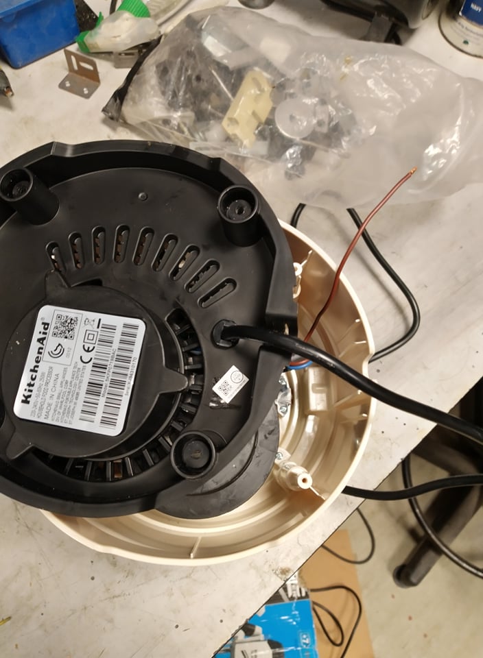
A soldered-in PCB fuse seems fair enough where its main purpose is to prevent fire in an already-failed circuit. But here, this is providing some motor protection function. It doesn’t seem right to have to strip down the machine and replace a soldered fuse after a motor overload, so I decided to fit a fuse holder with a 2.5A slow-blow fuse, equivalent to the one previously on the PCB. This will mean that next time I blow the fuse, I can just replace it and carry on! I was surprised that there seemed to be a lot of free space inside the machine, so I didn’t struggle to fit the fuse holder in.
Anyway, I hope this post helps someone else who’s run into the same problem.
Review
I thought this seemed like a good opportunity to share my thoughts on this machine.
I bought the 1.7l KitchenAid 5KFP0719 because I was in the market for a mid-range food processor. The main alternative I considered was the 2.1l Ninja BN650UK, with a slightly larger capacity and at a similar price (both around 100GBP). I ended up choosing the KitchenAid because it seemed to store more compactly, and they’re a brand I’ve had good experiences with.
KitchenAid are a brand I associate with high quality, well-built kitchenware. If you buy this expecting something on a par with their all-metal construction artisan mixer though, you’ll be disappointed. The base is made of plastic and generally it doesn’t give the impression of the same level of “finesse” I’d usually expect of the brand. Despite that, it say it strikes a good balance for the price: I’ve certainly seen far worse construction. The plastics appear to be good quality, although the bowl has started to go cloudy after just a few runs through the dishwasher. I accidentally put the pusher in the wrong way round and forced it quite hard. It got stuck and I was worried I’d have cracked the plastic, but in fact nothing broke.
The motor seems to have some kind of overload protection: after a few minutes, it will cut out. I assume this is to protect the motor from overheating. I guess this is one of the places they’ve cut corners to get the price down: put in a less powerful motor and over-stressed it, then included a protection to prevent it from failing. A very sensible choice. Lesser quality design would just put the overstressed motor in with no protection and expect you to just buy another when you leave it on for too long and burn it out. Obviously though, I’m a bit disappointed by the use of a PCB-mount fuse to protect the motor against a stall.
One annoyance is that, while it’s described as suitable for dishwasher, you need to make sure you put the bowl in the right way round: it has a hole in the base which allows water to drain out when it’s inverted. So it has to be tilted to allow water to flow out. If you put it in the wrong way round, the base fills up with a load of dishwasher water!
Overall though, I’m pretty happy with this for the price I paid for it (83GBP in January 2021). At full price though, I’d probably consider alternatives before buying this.
This is a followup to my previous post on retrofitting the Kenwood Chef A901 electronics to an A701a. I was quite happy with the result but the implementation was a little hacky. I decided it could be improved by designing a PCB for it.
Schematic Design
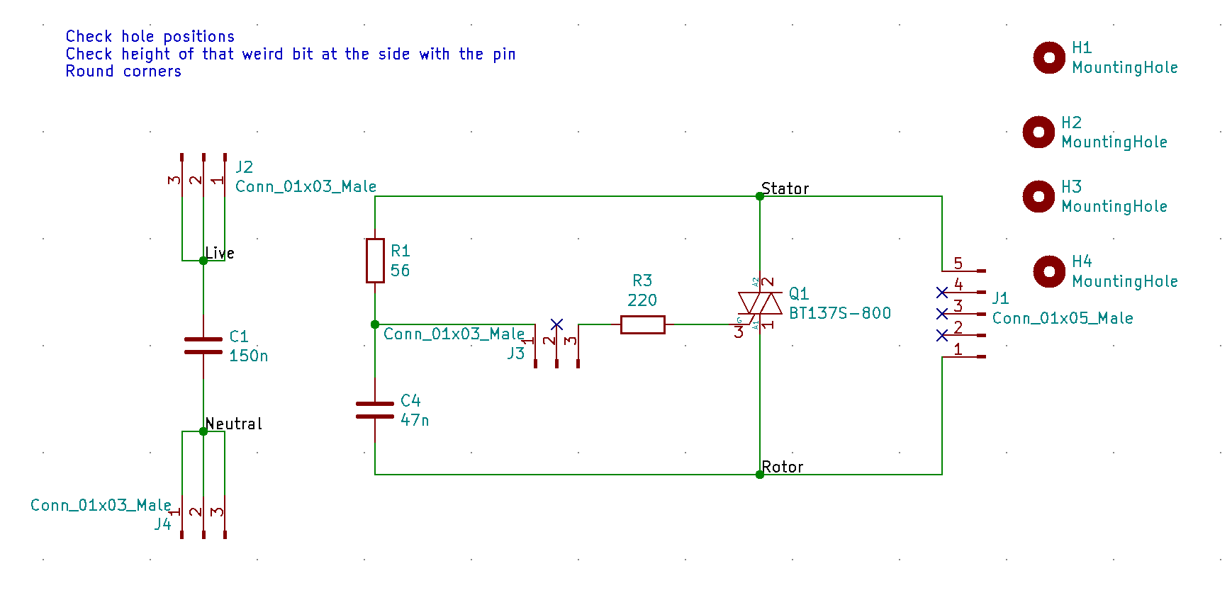
Conveniently, the BT137-800E which I’d chosen previously is available in a DPAK as well as TO220, so there was no need to consider component substitutions. I threw together a schematic in KiCAD:
For the resistors, conventional wisdom seems to be that the 56R should be 1W and the 220R should be 2W. To assess this critically, let’s have a think about what the currents might be. When the TRIAC is switched off, all of the potential will be between the nets labelled Stator and Rotor. When the TRIAC isn’t triggered, the only current path is through R1 and C4. At 50Hz, the 47nF capacitor will have a high impedance and the dissipation in R1 will be less than a milliwatt.
Imagine now that the TRIAC is triggered (the governor switch closes): we have up to 230V*sqrt(2)=325V across (56+220) ohms instantaneously. That’s up to 192W. However, the thyristor is specified to turn on within 2us typical:
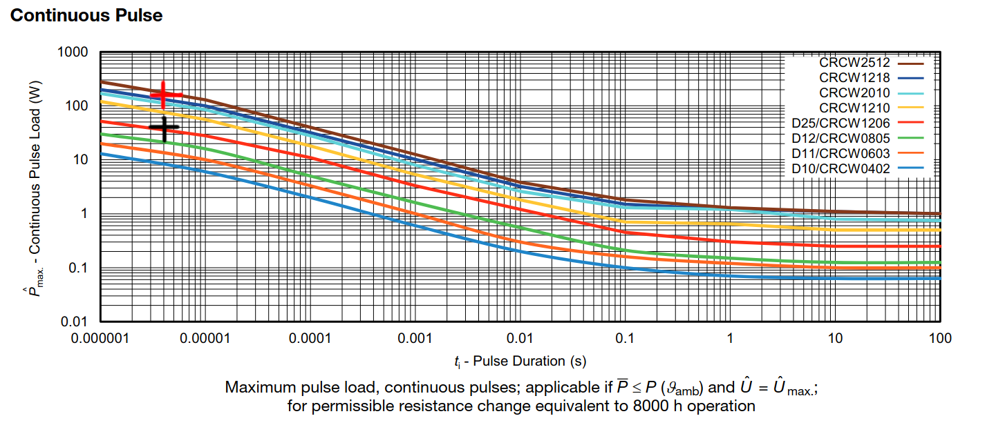
This would suggest an average dissipation, split between the two resistors, of 192W*2us*50Hz*2=38mW. In addition, when the thyristor is on, there might be up to 1.65V across the resistors, adding a further 10mW of dissipation. So clearly the rating of the resistors isn’t driven by average power dissipation. Instead, it’ll be driven more by voltage rating, and surge rating. The 56W resistor will see a maximum of 38W and the 220R resistor, 153W. Looking at the surge ratings for a CRCW chip resistor, it looks like sizes 1210 (0.5W) and up might be suitable for the 56 ohm resistor but even the 2512 (1W) is borderline for the 220 ohm:
Factor of 2 applied to pulse length, to account for lack of a maximum value in the BT137 datasheet (black cross for 56 ohm resistor, red cross for 220 ohm)
It seems sensible to apply a derating of around ~50% for long term reliability, so I selected a 2512 resistor for the 56 ohms (matching up with the conventional wisdom of using a 1W part!) and I decided that none of these conventional chip resistors would be suitable for the 220 ohm one. Instead I looked at 2W through-hole resistors.
It turns out pulse rating curves for through-hole metal oxide resistors don’t seem to exist. Instead, I found this from a panasonic metal-oxide resistor datasheet, which suggests that the only limitation on pulsed operation is that the average pulse power doesn’t exceed half of the rated continuous power, nor does the peak voltage exceed the pulse limit voltage:
Presumably this is due to the construction of the resistor allowing good instantaneous transfer of heat from the element, and perhaps the less miniaturised construction allows for less hot spots/pinch points. This would seem to suggest that even the smallest (1/2W or 1/4W) metal film resistors would suffice. However, curiously, the datasheet seems to suggest that this model is only valid for periods of over 1 second. I’m not sure why that is – I wonder if it’s a mistake and actually is intended to say T<1s? Otherwise this would suggest I could overload a resistor indefinitely, provided the average power constraint is met! Still, I decided to play it safe and use a 2W resistor, in case there’s something I’ve missed and so that I’m not relying on the pulsed voltage rating (only 2W and up are rated to 350V!).
I selected X-rated caps with a 250VAC rating. The 150nF cap certainly needs to be X-rated as it’s placed across the supply. The 47nF I’m less convinced about: X-rated capacitors are typically used in across-the line applications, but here it seems to essentially be decoupling the TRIAC gate. The other reason I’m aware of for choosing an X-rated capacitor is the self-healing effect following dielectric breakdown. That link suggests that around 100mJ is required to heal, which could be provided through the 56 ohm resistor in around 200us. Although by that point the resistor would already be fried, so you have to wonder if the X-rated capacitor gives any advantage vs a much more compact MLCC (eg a 47nF 500V 1206 X7R). Indeed, a common failure of the A901 is of the 56 ohm resistor, presumably for exactly this reason. Still, I erred on the side of caution and copied what was done on the A901.
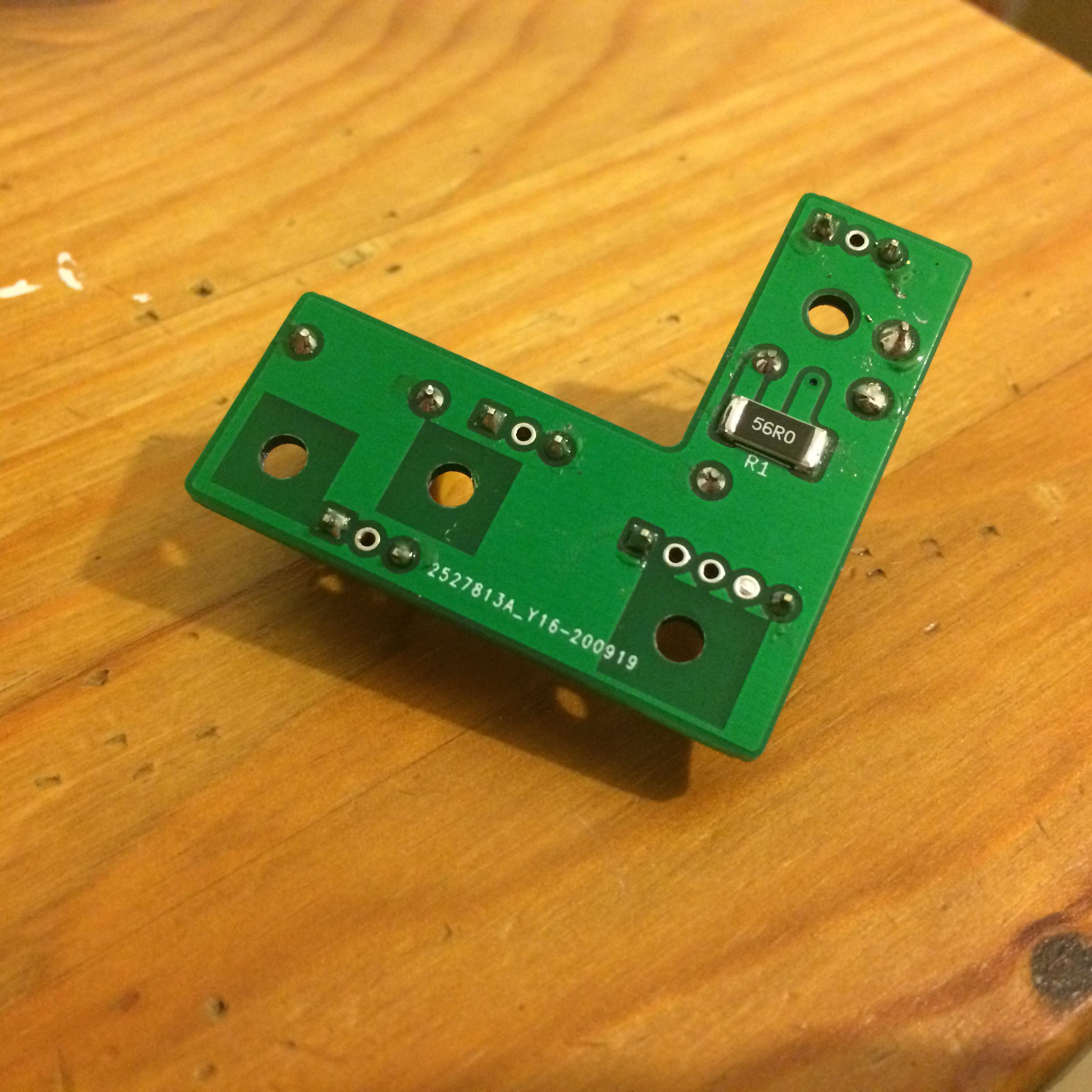
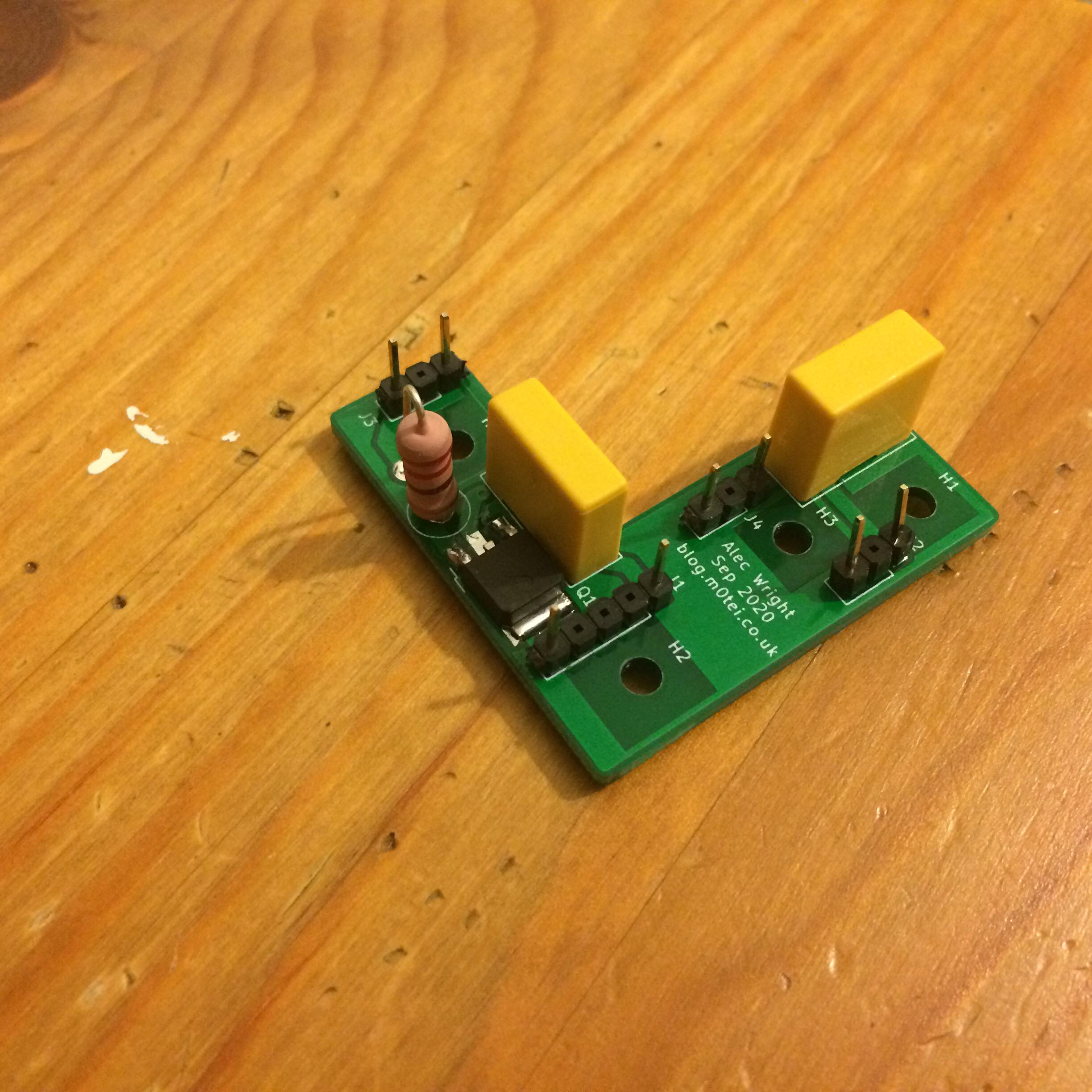
PCB Layout
Here’s the laid out PCB. I measured up the contact bar and designed the PCB around the size of that and the holes available for mounting. I had to drill (if I recall correctly) one of the holes out to 3.2mm, while the others were already the right size. Rather embarrassingly, I forgot to apply a copper keepout around one of the mounting holes on the bottom! Luckily though, I ended up using plastic mounting pillars anyway, so this didn’t really matter. In hindsight, I should probably have increased track-to-plane clearances or even removed the plane entirely (it serves no purpose other than habit and isn’t connected to a net!).
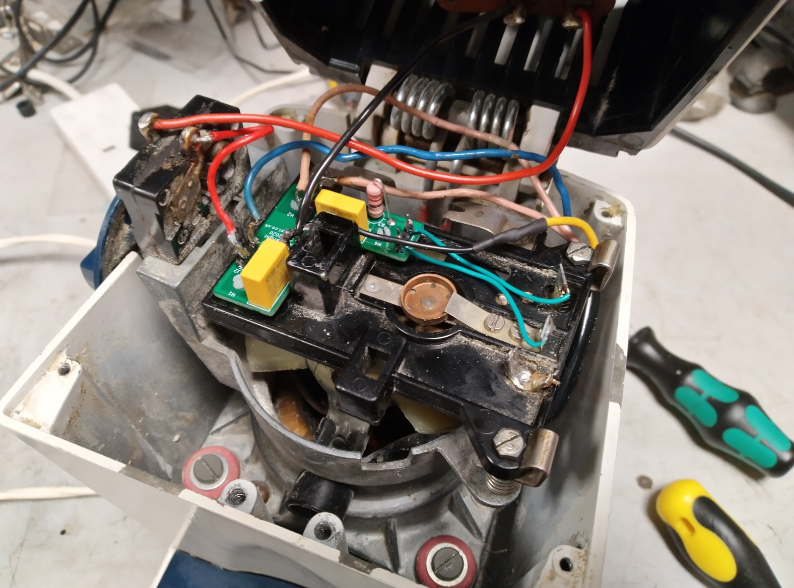
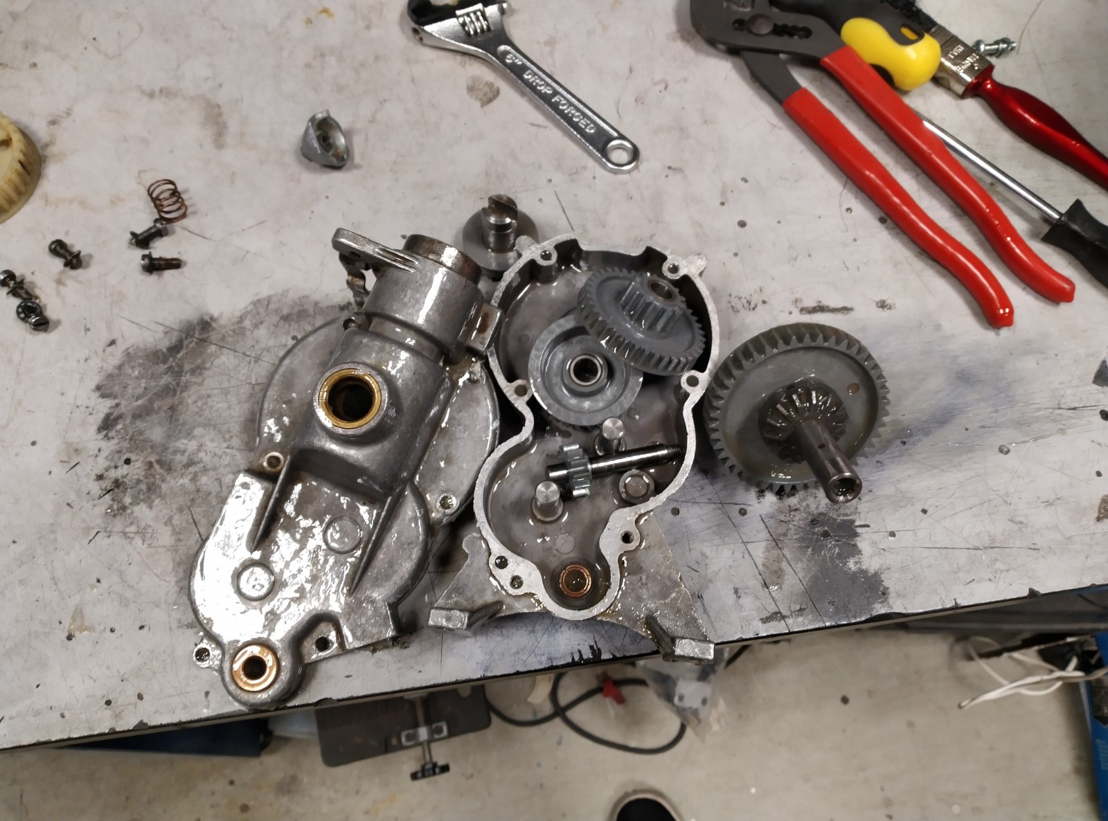
Gearbox Hell
You might wonder why the PCB has a date of September 2020 on it and I’m posting this in July 2021. It’s actually nothing to do with the circuit – that worked perfectly. It’s the gearbox where the problems started.
I decided to replace the grease in the gearbox, with it being around 50-60 years old. This ended up with me getting quite out of my depth with lubricant science!
Getting into the gearbox in the first place presents a bit of a challenge. Like the cassette on a bike, the nut on the dog clutch tightens during use and freewheels when you try to loosen it. To undo it, you need to jam up the mechanism to give you something to push against. I managed this in a vice with a screwdriver jammed in the planetary gearbox.
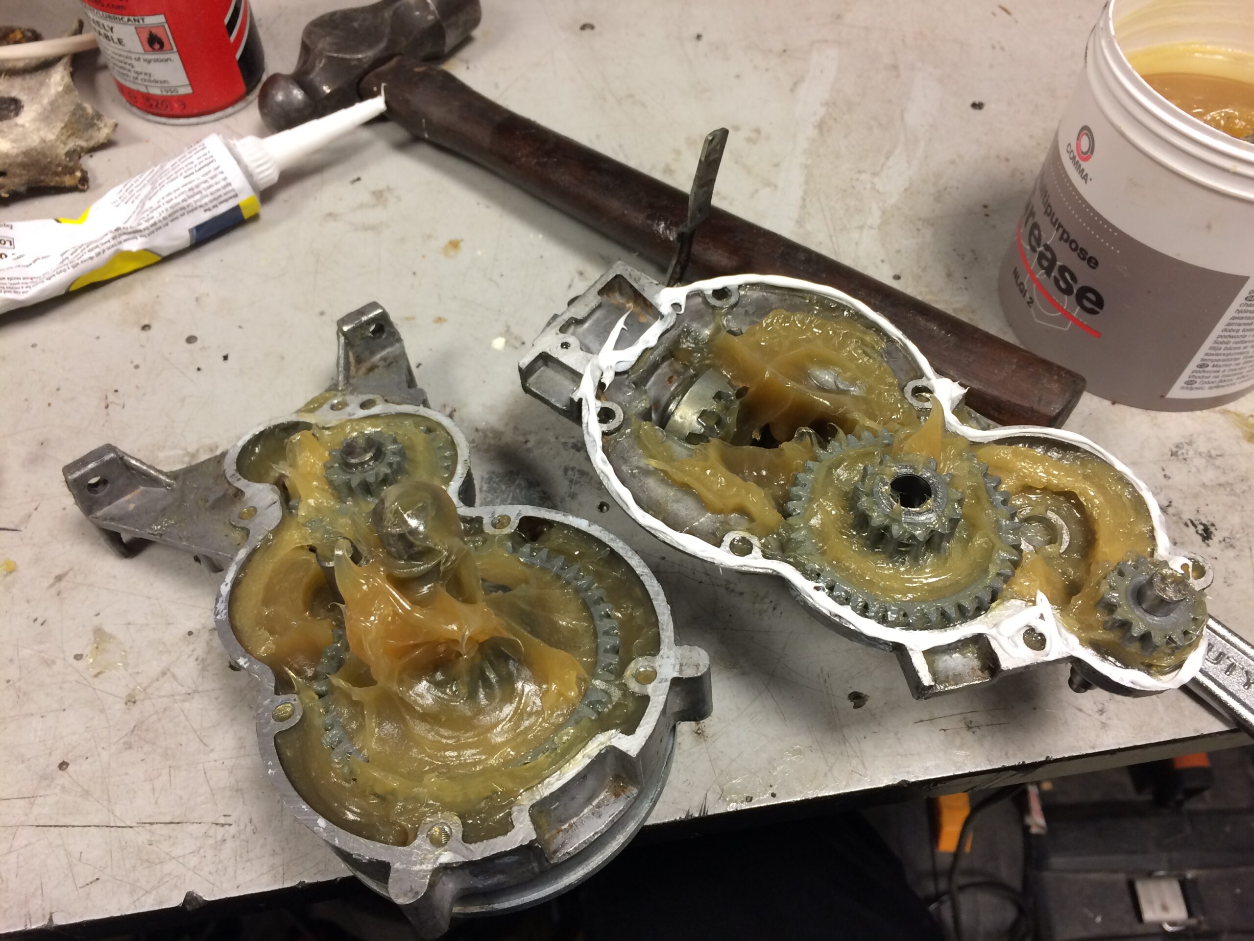
One thing I read about lubricants is that mixing different greases is fraught with danger. Unless you’re very careful you risk creating an inhomogeneous mixture, potentially with unexpected properties. From this, I reasoned that I needed to clean the old grease off pretty thoroughly first.
I removed the grease with tissue initially, and with white spirit and a brush to finish. Here are the parts mostly (but not completely) clean.
This is where it went wrong: I chose comma multipurpose grease simply because it was available easily and cheaply. I put it all back together with some silicone sealant around the outside.
When I reinstalled the gearbox, I found that it got quite hot while working and the mixer’s speed was limited to about 6 of the 8 arbitrary units marked on the speed knob (I didn’t think to actually measure the RPM – easy to do with just a stopwatch!). It was at this point that I realised I’d used too thick a grease and the project stalled for months as I couldn’t face opening and cleaning the gearbox again.
It turns out, the thickness of greases are measured on a scale referred to as NLGI consistency. While a simple oil is measured by its viscosity against temperature, greases are non-newtonian so it doesn’t make sense to define viscosity as a function of temperature alone. Instead, the NLGI consistency gives a more meaningful way to classify the response of a grease to shear forces.
The grease I’d selected had an NLGI consistency of 2. Looking through the service manual for the mixer, the specified grease is “Shell L.G.P.1”. While I couldn’t find any information on this (presumably discontinued) grease, the 1 at the end suggests an NLGI consistency of 1: in shopping for greases, I found the common nomenclature seems to be some kind of name and/or acronym, followed by the NLGI consistency.
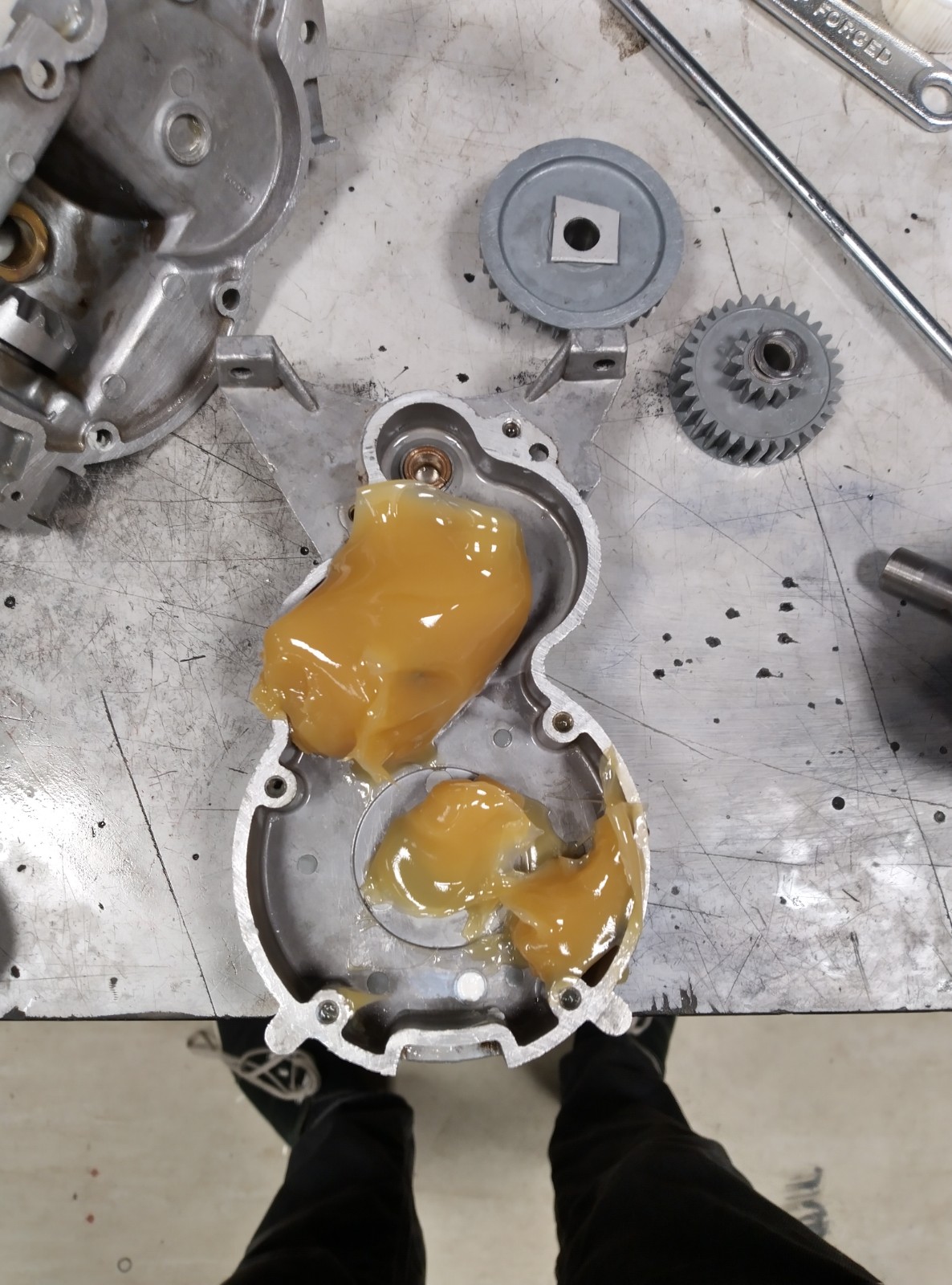
It turns out the market mostly comprises NLGI 2 greases. A lot of grease types seem to be only made in this one consistency, and the few which are available in NLGI 1 seem to be hard to get hold of in small quantities. I did eventually find one suitable grease though: Castrol Spheerol EPL 1, of which I managed to pick up a single tube online.
Eventually I summoned up the motivation to strip down and clean the gearbox again. Apparently this is the only photo I took where you can see the new grease, but you can tell from the smoother surface that this is, indeed, thinner.
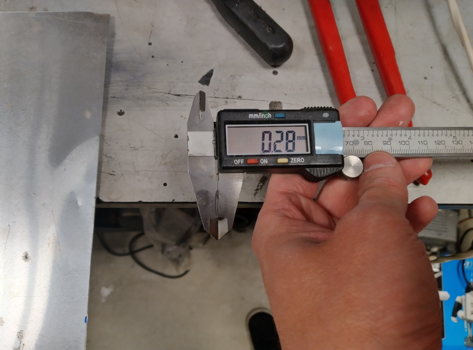
One snag was that I found one of the washers had gotten mangled. When I tried to bend it back into shape, it snapped. It was much thinner than a conventional washer (I measured it at 0.3mm thickness) and seemed to have an imperial inner diameter of 6.35mm – and since it needed to be a tight fit around the shaft, the next size up of metric washer wouldn’t be suitable. With no replacement lying around, I decided to bodge something.
I picked a piece of sheet metal from the scrap pile with a similar thickness and cut it down to fit within one of the gears. With such thin metal, I needed to clamp it between two pieces of wood as I drilled the 6.5mm hole, to avoid burring and bending of the metal. This seemed to work, and the gearbox moves freely.
Once I put everything back together, it went a bit faster than before but still slower than it should be: about 120rpm, when the service manual says that full speed should be 180-200rpm. I suspect the grease is still too thick: the original grease I took out of the thing still seemed thinner than the second lot I put in. If I was doing this again, I’d consider using NLGI 0 grease (the same Castrol Spheerol is also available in NLGI 0) but I think now I’ve run out of motivation to pursue this any more and I’ll accept that this is a mixer best suited to kneading dough rather than making meringues.
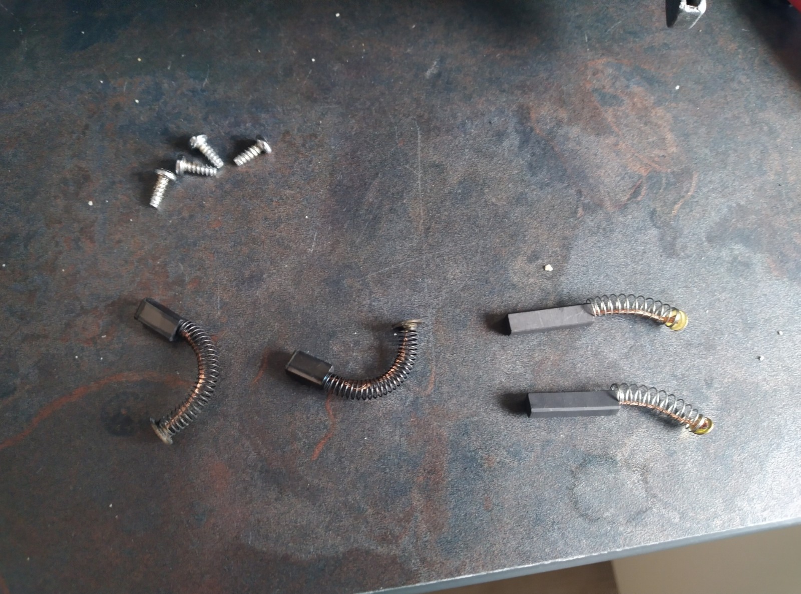
I did think that the speed might be due to friction in the motor: it didn’t seem to speed up much without the dog clutch engaged. I took the motor out and squirted a bit of oil into the bearings which seemed to increase the no-load speed, but it still slowed down to around 120rpm with the dog clutch engaged. At the same time I checked the brushes and found that they were quite worn. Since I had some replacements lying around, I switched them in.
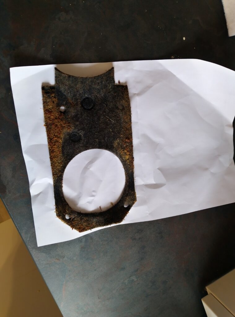
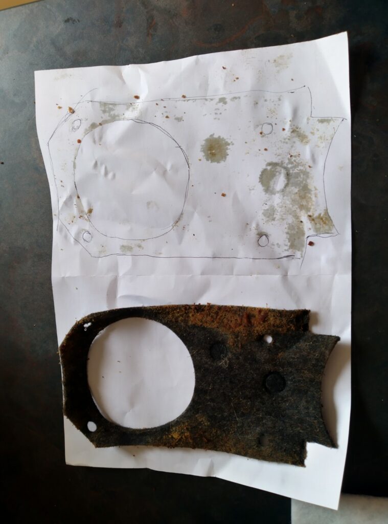
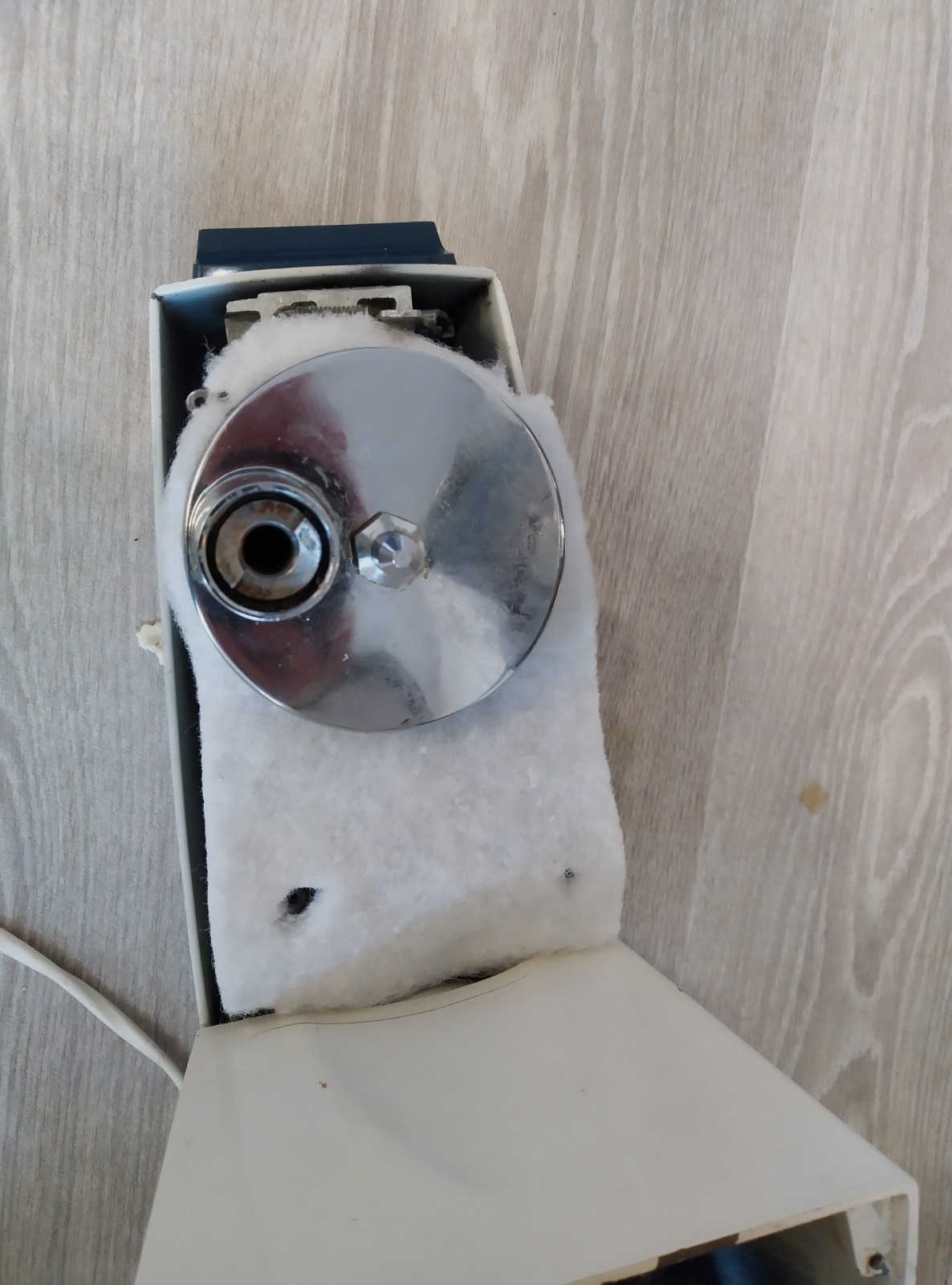
After replacing the rubber feet, the final thing to do was replace the felt. I had a piece of some kind of fibrous material lying around, I think a piece of cooker hood filter. It seemed to be quite good at soaking up grease, so I figured this would be suitable. I traced around the original greasy felt and used that as a guide to cut out a replacement.
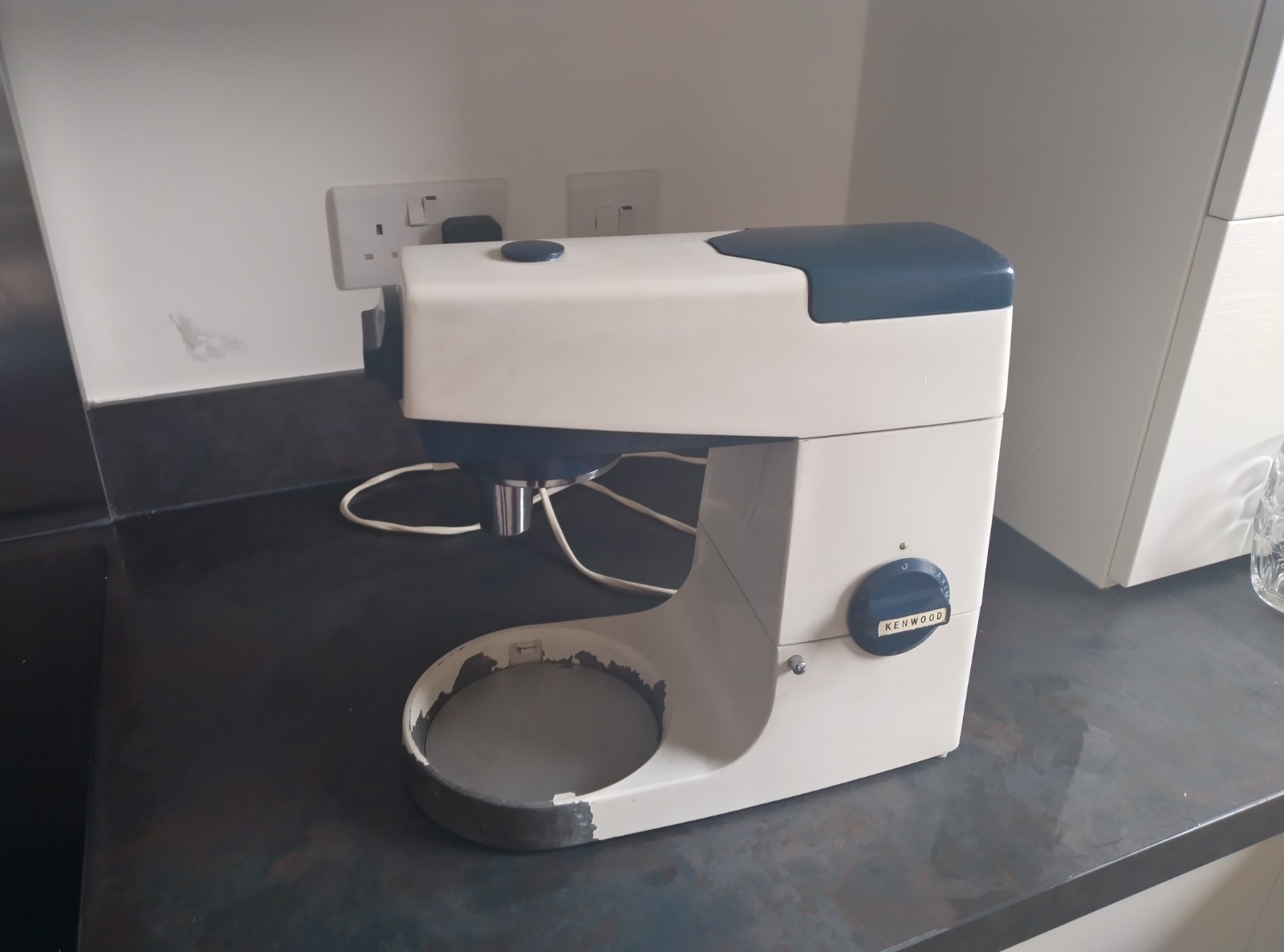
Here’s the finished thing. It’s been a learning experience! KiCAD project is available here.
I became aware of remote phosphors recently through a video on laser headlights by mikeselectricstuff where he shows a piece of remote phosphor in passing at about 5 minutes in. I’d never seen this material before and it got me interested in having a play around with it.
For a bit of background, there’s not really any such thing as a white LED. LEDs are essentially monochromatic as a result of the quantum mechanics which underpins their operation, which makes producing white light with an LED alone essentially impossible. One way around this is to use a red, green and blue LED in combination but by far the most common way to produce white light from LEDs is to use a blue LED and a yellow phosphor: the phosphor absorbs some of the blue light and re-emits is as various longer wavelengths, which appear as yellow. The combination of blue and yellow appears as white. The phosphor is typically embedded within the package of the LED.
The phosphor on the chip is what makes the LED in my Ikea lamp (left) and the light bulbs on my ceiling (right) to look yellow when switched off.
Remote phosphors don’t substantially change this, except that the phosphor is separated out from the LED. One potential advantage of this is that the remote phosphor acts as a diffuser, giving the light a softer glow and more even light distribution. Another is that they essentially remove the influence of the emitter on the quality of the light produced: if a remote phosphor is used, the phosphor gives the same CRI regardless of what blue LED is used behind it, allowing more flexibility with component substitutions. I bought a few Intematix Chromalit parts from digikey to have a play around with. The effect is really bizarre, as you can see below.
A bunch of 5mm blue LEDs, with and without an Intematix Chromalit CL-827-ELP30-PC bulb. It was really trippy to watch the light change from blue to white as you add the bulb!
My first target to make use of this technology was some LED downlighters which came with my flat. These are pretty awful, producing flickery light.
I thought these were GU10 or MR16 but actually when I took them apart I found that the bulbs are some strange proprietary type called G40. Despite being apparently purpose-built for LED bulbs, the fitting seems to suffer all of the failings of LED retrofits: the compact form factor places hot LEDs next to a hot driver circuit, reducing the reliability of both, and the lack of space leads to insufficient decoupling and large amounts of flicker. This seems like a stupid design decision when the ceiling space gives ample opportunity to separate out the driver.
The fitting and its original bulb: an 8132 5W G40 lamp, produced by tp42.
I ordered some 5W blue LEDs and a constant-current driver module off aliexpress and fitted these in the original fitting. The phosphor I use here was CL-927-LR-PC: 90CRI at 2700K so it should produce a very good quality warm white!
For an initial test, everything’s held together with parcel tape! I had to cut a little bit of the phosphor off to make it fit. Anyway, looks like it’s all working fine.
The remote phosphor is glued down with gorilla glue and weighed down with a watering can while the glue sets! I tried scratching off the paint in the fixture to improve thermal contact from the LED but without much success. The LED’s bolted down with two woodscrews and some thermal transfer compound.
Installed. Success!
I’m pretty happy with the outcome, at least for a first attempt. The quality of the light seems good, although what isn’t obvious from the photos (given the camera’s auto-exposure) is that it’s not quite as bright as I’d hoped. I used a 600mA LED driver with a 2x series LED package, for about 3.6W. The light it replaced was 5W. I’ve ordered a larger 3x series LED package and a driver to suit it, so in the future I’m going to have a go at upgrading the LED. I think I might also need to have another look at the thermal design. The transfer from the LED package to the fitting case doesn’t seem great. I’m hoping I can find some way to scrape off the paint and improve contact.
Having done this, I’m inspired to have a go at using this material for some other projects: it’s also available in strips, which I think I might use for some under-counter lights in my kitchen.
I found this weird extension lead dumped at the side of the road this evening.
It looks like a normal 4-way extension lead but for the bit in the middle with the “GreenPlanet” sticker and a curious “SMALL/BIG” switch on the side. There seems to be no information on the exact model anywhere on the internet, but the model number is “TL0893INFOB”. I wasn’t sure what this was about at first but I know there’s a lot of snake oil sold around magic “energy saving plugs” so I knew the possibilities were endless and it was certainly going to be something stupid. From the “master” and “slave” labels I figured out eventually what its purpose must be: to turn off the phantom load on the “slave” sockets when the “master” is switched off. When I got home I googled it and my suspicions were confirmed. The reviews I found for this thing (or similar devices under the same brand) were almost universally negative, with complaints including:
Doesn’t switch off devices when the master is switched off
Randomly switches off “slave” devices while the master device is on
A loud hum while it’s working
I’ll admit: I didn’t fully test it before I took it apart. I meant to but I tested it with a laptop charger and it turns out my laptop isn’t great at telling you when it’s plugged in so I got entirely false negative results and assumed there was an internal short blowing the fuse. I did notice though that plugging my laptop into the master socket didn’t do anything (no indicator light, no sound of a relay closing), which is probably why it got thrown away.
Taking it apart, it’s exactly what you’d expect: a board with some crude load detection circuitry and a relay.
I had absolutely no interest in reviving the magic power saving circuitry so I just ripped it out. It didn’t look interesting enough to fully reverse engineer but it looked like a cement resistor (which I ripped off while removing it) measured the current to the master socket, the circuit would detect this above a threshold and switch on the relay to enable current to the “slave” sockets. I’m not sure what the SMALL/BIG switch does but I wouldn’t be surprised if it’s a threshold selection. The power supply seems to involve a capacitive dropper. The IC in the middle is an LM324 quad op amp and there’s a 2N5551 which I suspect is activating the 24V relay. I wonder if the mains frequency ripple across the relay coil is the cause of the noise which some reviewers complained about.
With a couple of terminal blocks, the circuit is bypassed and it’s just a normal extension lead. If I had the desire to, this could have been a fun project for making a “smart plug” with the convenient place to install the circuitry.
I’m always looking for an extension lead so this was a handy find, and interesting to take apart too. It was always a stupid idea because it’s overcomplicated. Instead of something like this, it’s more important for new equipment to be designed with low standby power, eliminating the need for this kind of trickery. The drawbacks are too many: essentially there’s no reliable way for it to tell if equipment is “on” or “off” and the inclusion of the “SMALL/BIG” switch makes it user unfriendly by giving you another hurdle to cross before you’re able to use it. I’m not surprised it ended up dumped at the side of the road.
Everything breaks at the most inconvenient time – that’s a fact of life. So it’s hardly surprising that I discovered my power bank was broken on a several-hour long train/bus journey. Once I got home, I decided I’d fix it.
The opened power bank
Opening it up, I could see the circuit was divided into two boards: one with the battery and the charging and protection circuitry, and one with the boost converter. I didn’t do too much reverse-engineering of either board but I did discover that the boost converter board had a logic input from the charging/protection board, which enabled or disabled power to all of the circuitry.
The problem seemed to be that nothing would make the protection board drive this high. It has a button to switch it on and, even with the battery fully charged, it would just blink its LEDs to tell you the battery was flat when you pressed this button. Connecting the boost converter board to a bench power supply at 4V and pulling the enable input high, the converter was working fine. So the fault seemed to be with the battery protection.
Rather than bypassing it completely and sacrificing all protection on the battery, I figured an adequate protection for the battery would be an undervoltage cutout. It should cut out at around 3V. It should have some hysteresis too: once the load is removed the battery voltage will recover a bit. I don’t want this to cause oscillation. Once it trips, it shouldn’t reset until the battery’s recharged a fair bit. For this, I’d set a rising threshold of 3.6V.
To achieve this I’d need a low-power comparator and a reference. I thought my chances of finding something lying around were pretty slim – and I didn’t think this project was worth buying parts for. Power banks are easy to come by and if I couldn’t find the stuff to fix this right now, it would have just gone in the bin. So it’s lucky that, looking through a drawer of “Misc ICs”, I found a MAX931:
MAX931 datasheet snippet
An ultra low-power comparator with internal reference was exactly what I needed! And the supply voltage range conveniently covers the 3V-4.2V range over which I need this to work. The circuit I used is a very simple comparator circuit with the inverting input fed from the internal reference. The “HYST” pin controls an internal hysteresis. I decided not to use that – the maximum hysteresis it can add is around 10% but I want closer to 20%. Instead, I achieve the hysteresis by adding a feedback resistor.
For the falling threshold of 3V and the rising threshold of 3.6V, I want a nominal 3.3V threshold (halfway between the two) with a 600mV hysteresis. R1 as 1M and R2 as 560k means the non-inverting input would match the 1.182V reference at the inverting input with an input voltage of 3.29V – pretty much spot on the nominal threshold I was looking for. Divider current will only be about 3.7V/1560kohm=2.4uA. Compare this with the typical input leakage of 10pA with a maximum of 5nA over temperature: this divider current is enough that input leakage can be ignored.
The low threshold is the most critical one, so I calculated the hysteresis based on this. We want to trip at 3V. At 3V, the Thévenin equivalent of R1 and R2 would be a 3*560/1560=1.077V source, with an impedance of 560||1000=359kohm. To bring this up to the 1.182V reference and make this trip, we need to deliver a current into it of (1.182-1.077)/359k=292nA. For output currents <1mA or so, the output will more or less be at the rail:
Datasheet snippet
So the feedback resistor needs to be set to deliver that 292nA with 3V-1.182V across it. That means for R3 we’d like (3-1.182)/292n=6.23Mohm. 6.8Mohm was the closest value to this that I had so that’s what went in. The current draw of this circuit will be around 5uA, about equally split between the potential divider and the comparator quiescent current. The battery is supposedly 5Ah – if that’s the case this circuit will take around a million hours or 114 years to fully discharge the battery.
I threw the circuit together on breadboard:
Circuit with LED to indicate state
I cranked the voltage up and down to check the trip points and as expected, the output would switch on at about 3.6V and off at about 3.0V.
This is far from my finest soldering job but I airwired all the components together:
Circuit before adding a 47nF decoupling capacitor
I’m never going to need to charge four devices at once, so I removed a couple of USB ports to make space for this circuit:
I’m not sure that anyone actually needs to charge four devices at once from a powerbank. I suspect the number of USB ports is partly a historical thing: I remember a time when a lot of USB devices were very picky about what a charger did with the data lines. You can see in the above picture that the ports are labelled with different current ratings and have different resistor networks between D+ and D-. All of my devices charge fine from all of these ports so I just removed the two ports labelled with the lowest currents and wired the circuit in.
This was a real mess and I’d accepted that this is a total bodge job – hence the comparator wrapped up in insulation tape.
I found that the boost regulator, when idle, would draw around 24mA. This would run the (supposedly) 5Ah battery flat in a little over a week. For this reason I bodged a switch in series with the enable output, so that the power bank could be switched off when not in use.
The end result is a mess. But it works. And it has a switchy switch! It goes click! Waste not, want not – hopefully it will last me a little while longer now. Until it breaks at the most inconvenient time – but I guess that’s just a fact of life.
I’ve finally managed to switch electricity suppliers! It’s been a long journey, and I described some of the background in my previous post. In this post, I’m giving an update on my journey, I’ve written a guide on how to follow in my footsteps, and I’ve added a few more practical thoughts related to these meters.
My Journey
As I mentioned in my previous post, suppliers other than scottish power are only required to offer me single rate tariffs: meaning I’d be unable to take advantage of cheap night time electricity for my space and water heating. Even in light of this, my scottishpower tariff is so expensive that this still works out cheaper than staying with them. The company I ended up switching to was Octopus: simply because they were the cheapest “big name” supplier for a single-rate tariff with my ~5300kWh/year usage. This turned out to be a good choice, as they did an amazing job of supporting me with my switch.
I initiated the switch using MSE’s cheap energy club and then emailed them immediately to make sure they had all the relevant information about my meter (both of the MPANs) and check that they’ll only be charging a single standing charge. They initially told me they’d be doubling my standing charge on account of my dual MPANs, but I cited the “Energy Market Investigation (Restricted Meters) Order 2016” and I never heard anything about the notion of doubling my standing charge again.
Once I got talking to Lucas at Octopus, I was surprised that he was able to offer me a 2-rate tariff. I was delighted at this since it means I can save a lot more money than I was ever expecting! The switch took a little bit longer than it should have done because of problems with the MPANs not being switched at the same time and scottishpower objecting because of this, but I think lessons were learned and this is all ironed out now.
Unlike on scottishpower, my octopus account shows my two MPANs as if they’re separate meters:
My octopus dashboard
One MPAN works exactly as if it were an economy 7 meter, taking two meter readings (my day and night rate readings). The other MPAN also shows as being on the dual-rate tariff but I only submit one reading for it: my control reading, which gets charged on the night rate. I’m actually getting billed separate standing charges for each MPAN, but I was credited with a year’s worth of standing charges upfront so one standing charge is effectively zero. I haven’t been with them long enough yet to have received a bill, but when I submit meter readings my account balance gets reduced by the correct amount, so it seems like their billing is working fine! Since it’s the middle of summer, I haven’t used any control rate electricity though, so I can’t test that yet.
I’m really pleased with the outcome of this – I was never expecting to be able to escape scottishpower so this is a huge relief. I hope this information helps other people to make a choice with their restricted meters. Octopus have gone above and beyond their duty: all that Ofgem require of them is to offer me a single-rate tariff. I doubt it’s been worth their time and expenditure dealing with me, yet they’ve put me on a fair, dual-rate tariff which they had no obligation to do. The overhead of managing my meter probably outweighs any profit they’ll make from selling me electricity, but I think this is the fair thing to do: for suppliers to take the hit on the overhead associated with legacy infrastructure rather than this being passed to unwitting customers. I hope Ofgem make changes to reflect this in regulation and improve choice for us in the longer term.
Guide to Switching
This guide applies to anyone on exactly the same kind of meter as me: Scottish Power Comfort Plus White Meter. Please feel free to try it with any other restricted metering infrastructure and let me know how you get on! I know of someone else trying this with an SSE THTC meter now too.
Bring your account up to date and in credit with Scottish Power. They may object to your switch if your account is in debt so submit a meter reading and, if you can, make a card payment to put your account comfortably in credit. This may be easier said than done in these times, but reducing the debt may still help if you’re able. Bear in mind that you might not get any credit balance refunded for up to 11 weeks from when you start your switch, so budget for being without the money for that time.
Decide whether you want a single-rate or dual-rate tariff. If more than half of your electricity is on your night or control rate, a dual rate is probably preferable. Check your scottish power bill and you should have a summary of your annual usage. You can see mine at the end of this section, for example. My night+control rate summed together are 1892+2124=4016 – way higher than my day rate of 1348. So in my case, a dual rate tariff was definitely the right choice
Decide which supplier you want to choose. Long story short, I’d recommend choosing Octopus. Admittedly, I do stand to gain if you use my referral code further down, but even if this weren’t the case, I still think they’re probably the easiest supplier to deal with if you have a restricted meter. Their rates are very competitive at the moment too. If you’ve decided you want a dual-rate tariff, as far as I’m aware the only option at the moment is Octopus. It might be worth comparing other suppliers’ economy 7 tariffs and asking them if they’ll supply your meter and with what charges, but be prepared for disappointment! If you’ve chosen a single rate tariff, you’re theoretically able to use any supplier, except for some smaller suppliers. You might want to compare suppliers using a tool like cheap energy club. Make sure to choose “show only big-name suppliers”, because this will exclude the ones who are too small to be required to take on your meter. Theoretically, your switch should be seamless but it’s likely you’ll have to contact them to confirm that you do indeed want their single rate tariff, and to make sure that they transfer both of your MPANs without charging the standing charge twice. Because of all of this, you might prefer to choose Octopus even if you want a single-rate tariff.
If you’ve decided you want to switch to Octopus, it’s best to email them since a restricted meter switch will require some manual intervention on their end. Hopefully it should all be seamless for you though! Email hello@octopus.energy and ask for Lucas – he dealt with all the quirks of my meter and he’s probably now Octopus’ expert on restricted meters! They’ll need your name and address to start the switch. If you know someone currently on octopus who can refer you, you’ll both get £50!
Submit your initial meter readings with your new supplier as soon as they ask you for them, to maximise your savings
Annual usage example
Other Things to Consider
A few other things you might want to consider when selecting a supplier or tariff, or after you’ve switched:
If you’re asking for a dual-rate tariff, you’re relying on the willingness of the new supplier to support this. As far as I’m aware, no supplier is obliged to do so. If you don’t stand to gain much from a dual-rate tariff, you might find it easier just to just choose a single rate.
Consider how you might change your energy usage. If you’re on a Comfort Plus White meter tariff as I was previously, chances are you use most of your electricity at night since the rates strongly incentivise this. But maybe if you were on a single rate tariff you’d be able to reduce your consumption, and slightly offset the loss of a cheap night rate? For example, maybe you often find your storage heaters are wasting a lot of energy heating your home when you don’t need it? If so, perhaps you could stop using your storage heaters and switch on a plug-in heater as you need it instead. Or maybe you’re heating a full tank of hot water overnight then finding that you don’t need it all? Maybe stop running your immersion heater overnight and just hit “boost” when you need some water. While this is all generally bad advice if you’re able to get 2-rate electricity, you might decide that the hassle of securing a 2-rate tariff outweighs the savings. Before I found I could get a 2-rate tariff, I was planning to do all of these things and decommission my storage heaters!
Something I haven’t looked in to yet is whether the process of a meter change is easier after switching. I wouldn’t rely on this but once you’ve switched, it’s probably a good idea to discuss with your new supplier about the possibility of changing your meter to a more standard one. If you can do this, it will probably make switching easier next time. There’s a risk of this being difficult if you’re renting but it may be possible – especially if the replacement is also a smart meter, as I don’t think it’s possible for a landlord to object to a tenant getting a “dumb” meter being replaced with a smart meter.
Conclusion
All of this restricted metering nonsense has consumed a lot more of my time and energy than I’d expected. I think I’m about to wrap this project, but before I do I’m going to contact an organisation or two to try and “pass the baton” in terms of looking out for restricted metering customers. I hope what I’ve discovered helps someone else follow in my footsteps and raises more awareness of the struggles associated with these meters. If anyone else tries this approach, I’d be interested to hear how you get on!
For most people in the UK, switching electricity and gas suppliers is an easy process – and you can save yourself a lot of money by comparing your options regularly and considering switching. I’d recommend Money Saving Expert’s Cheap Energy Club as a very easy-to use tool for doing this.
However, for a few of us, the options are much more limited. When I moved into my current flat in Edinburgh, I had to deal with a Dynamic Teleswitch Meter, a form of “Restricted Metering Infrastructure” – as Ofgem refer to it. Essentially, the meter has two circuits with three associated rates: one circuit behaves in a similar way to economy-7, being active all the time but switching between a day rate and a cheaper night rate at fixed times of day. The other circuit is switched on and off at the behest of a radio teleswitch signal, and only supplies my storage heaters. The switching times of this aren’t guaranteed – it can be anywhere within a certain window, but must be at least a certain number of hours per night.
My “Comfort Plus White Meter”, plus right hand fuse box for storage heaters and left hand fuse box for everything else
I suspect this form of metering was introduced before the electricity market was changed such that it was possible to change suppliers and so this wasn’t a concern. Technologically, the benefits are apparent: the grid have some flexibility over when they provide power for storage heaters, and this can be used for load balancing. The consumer is rewarded by a slightly lower rate for heat units vs night time electricity. For example, my current tariff is:
Rate
Approx usage/yr
Approx cost/yr
Day
24.223p
1276kWh
£309.09
Night
11.535p
1875kWh
£216.28
Heat
10.469p
2169kWh
£227.07
Standing charge
22.57p
365 days
£82.38
Total
5320kWh
£834.82
The “approx usage” I’ve given is based on my usage over the last 12 months. I’m not sure if this is high or low. Scottish power tell me I’m a high user, and MSE would have estimated my usage at about 1/2 of what it is. But also I live alone in a 1-bed flat which visitors complain is cold in winter, and I think I’m quite frugal with electricity – running washing overnight when I can and avoiding heating water on daytime electricity. So who knows. Anyway, this table illustrates the overarching problem with these meters: the tariffs available are uncompetitive. When I’ve tried to switch before, scottish power have told me that there are no alternative tariffs available from them. Other suppliers have said they’re unable to take on my supply, or are only able to offer me a single rate: to which I said no thanks, because running storage heaters on single rate electricity would be stupid, surely? To see just how bad a deal I’m getting, let’s imagine I had an economy 7 meter and all of my heating usage was on night rate instead, as is typical for storage heater installations. This is Vari-Fair by Bulb — the best deal I found from MSE’s comparison:
Unit rate
Estimated usage/yr
Estimated cost/yr
Day
16.46p
1276kWh
£210.03
Night
8.705p
4044kWh
£352.03
Standing
20.558p/day
365 days
£75.04
Total
5320kWh
£637.10
So I’m paying around £200 extra per year because of this meter, compared to if I had economy 7. In light of this, I decided it would be worth trying to get the meter replaced, even if I had to incur some of the cost myself. I contacted Scottish Power and asked them whether I could change my meter (with my landlord’s permission) to an economy 7 one. I was repeatedly told that they’d be happy to change my meter, but only if I removed my storage heaters – they insisted that storage heaters could not be used with economy 7. Clearly this is an outright lie – the very point of economy 7 tariffs is to work with storage heaters. I asked them what other options I had for heating my home. I expected them to insist that I needed to use panel heaters, but instead they made the baffling claim that no form of electric heating could be used with an economy 7 meter, and so I’d need to remove electric heaters entirely. Eventually, when I agreed that they could disconnect my storage heaters (with the intention of getting an electrician to reconnect them with a timer afterwards), they told me they’d phone me within a few weeks to arrange replacing my meter. This was over a year ago and I’ve never heard back.
DTS customers often don’t understand how their meter works
Customers often didn’t choose to have their meter installed
Customers who had tried to switch tariffs had often given up in frustration
Tariffs are uncompetitive
As well as this, they found that DTS users are typically elderly, less affluent and less educated. This is worrying from a fuel poverty perspective – in that those who are more likely to struggle with fuel costs are also more likely to be taken advantage of through these tariffs. I’d be willing to bet that a lot of them are renting too, so need for landlord’s permission is another barrier to escaping these meters. The latter report is dated 2014, and I thought it seemed strange that six years later I was still suffering the same frustrating experience, so I contacted Ofgem to ask what they’ve been doing for DTS customers since then. They pointed me to a piece of legislation: Energy Market Investigation (Restricted Meters) Order 2016. This requires that electricity suppliers (with the exception of small suppliers serving fewer than 50k households) offer single-rate tariffs to customers with restricted meters, at no extra cost. This is far from perfect, as a single-rate supply is unlikely to be cost effective for running storage heaters and water heaters, but it’s a start. I was curious, so looked in to just how bad it would be to run my home on single rate electricity. Searching for single rate tariffs with an annual usage of 5320kWh, I found that the best deal was available was Symbio Energy’s “Low, Fair and Green 2020 Variable v7”:
Unit rate
Estimated usage/yr
Estimated cost/yr
Single rate
11.055p
5320kWh
£588.13
Standing charge
24.5p/day
365 days
£89.43
Total
£677.55
Amazingly, it seems like it would still be cheaper to accept a single rate rather than stick with Scottish Power! And that’s even with about 75% of my electricity usage at night, which is well above the national average. If my daytime electricity usage was higher, my current tariff would be even less competitive. However, Symbio are a small supplier and might not be required to take on my restricted meter (if they have fewer than 50k customers). Even still, there are plenty of single-rate tariffs available from big-name suppliers which would cost <£800 a year, so still a small saving compared with my current situation. And like all of the other tariffs I’ve compared here, some of them have no exit charges.
I’m now trying to switch to a single rate tariff. I’m not expecting it to be easy but I’ll see how it goes. When I’ve tried to switch before I’ve run into problems with dual MPANs — so this time I’ve made extra sure that I’ve made the new supplier aware of that. I hope that the situation improves for consumers with DTS meters. Especially with smart meters being rolled out, this could be a good opportunity to allow such customers more flexibility. While I’ m not particularly familiar with SMETS2 meters, my understanding is that they have multiple switched outputs and so could be programmed remotely to switch between DTS, single rate or economy 7 tariffs. I hope that Ofgem will consider taking advantage of this and pushing further legislation to allow us this flexibility and protect us from exploitation. Because what is happening now feels like exploitation of a captive market by Scottish Power, and a cynical attempt too hold on to these customers. The “state of the market” report by Ofgem sugests that 551k homes have DTS meters UK-wide, including 91k in the south of Scotland. We’re constantly reminded of the need to compare energy suppliers in adverts by price comparison sites. But half a million homes don’t have this option. Hopefully there are brighter (and warmer!) days ahead.
Following on from my previous post, I gained another addition to my mixer family: a kenwood chef A701a.
Latest addition to my collection on the right
I got this as spares/repairs and when I opened it up, one thing was obviously wrong: it seemed to have swallowed half a bag of flour:
Vacuuming this up was quite satisfying…It was everywhere
Once I got it cleaned up, it turned out the fault was just a wire loose. The solder joint had snapped, I suppose. With this soldered back on, it lived again!
Broken wire – the neutral wire from the motor
Running it at a low speed, I could smell the residual flour burning off the 450 ohm wirewound resistor. This got pretty hot in low speed operation because at lower speeds it alternates between having this resistor in series with the motor, and shorting it out. From my research previously, this resistor seems to be the most common failure in these mixers. Aside from that, it’s wasting a tonne of power and making the motor hotter than it needs to be, so it worried me a little from a motor reliability perspective too. I realise it had worked fine for 40+ years and the chances are it would continue to be fine, but I thought it would be a fun project to try and retrofit the A901 TRIAC motor controller to this model.
The other reason I wanted to make this modification was that the design required the physical switch on the motor controller board to switch the full motor current. There’s some suppression circuitry which I suspect is partly to reduce the stresses on that switch, but it still gave me the fear – you could even see it sparking as the motor ran! The TRIAC controlled version, on the other hand, only carries the TRIAC gate current through the switch so the stress on the switch is more or less zero.
This snippet from the service manual shows the wiring of the mixer:
The input chokes don’t exist in my model. Also nor do any of the supression capacitors, except the 0.1uF across the resistor (value not labelled but it’s 450 ohm)
I can only assume the chopper circuit is placed in between the field and rotor windings to take advantage of the interference filtering offered by the windings of the motor – since it’s series wound it makes no odds electrically where it’s placed. The same is done on the A901. I haven’t found a service manual for this but I’ve reverse engineered the following schematic:
The switch in series with the gate is the one controlled by the centrifugal governor. It gets pushed open when the motor hits its target speed.
Since the A701a and the A901 are very similar and the motors seem to be more or less the same, I figured I’d just reproduce the A901 circuit verbatim and see if it works. I found this old solder terminal board on it lying around, and I thought it seemed ideal for this circuit. I already had the components as spares for my A901s. The TRIAC in the original circuit is unknown and has some non-standard marking, so I took a punt on a BT137-800E. In this simple circuit I suspect all triacs with a sufficient voltage and current rating are much of a muchness, and the 800V, 8A rating of this seems like it should be plenty.
I disconnected the motor controller circuit on the mixer and placed this new circuit in instead. It works! Here I’m just using a crocodile lead to simulate the switch actuated by the governor so there’s no actual speed control.
I captured this interesting video too, where you can see how the governor works:
With the basic circuit working, I set about figuring out how to fit it. First, I ripped out the old motor controller components, just leaving the board with the switch:
Next, the TRIAC needed mounting. It didn’t seem to get noticeably hot at all, but since the mixer has plenty of space inside it, I thought I may as well give it some heat sinking just to be on the safe side. I used one of the holes in the board to mount it onto a random bit of aluminium angle I found lying around, with a thermal pad to act as a gap filler:
I found this random bit of metal which conveniently fitted in the pillar which supported the capacitor, and retained an M3 screw:
With the circuit bolted down, annoyingly the TRIAC leads didn’t reach to any of the solder terminals:
This may have been a blessing in disguise though since I’m not sure I’d have been comfortable with the solder joints being exposed to the potential stresses caused by vibration in the mount. Anyway, I wired up the TRIAC with short lengths of wire instead. I’ve also wired in the switch.
And now putting it back together and soldering the various motor/mains input/switch wires:
And it works! Another happy mixer! It gets a lot less hot at low speeds now
I’m pretty happy with this result! If I end up getting another one, I’m tempted to do a bit more of a polished job of it by designing a PCB to go on the old board, and possibly make it easier to upgrade more of them. It seems like A701s appear with broken motor controllers from time to time, and the wirewound resistor is expensive to find a replacement for. Replacing just a PCB could be a good alternative…

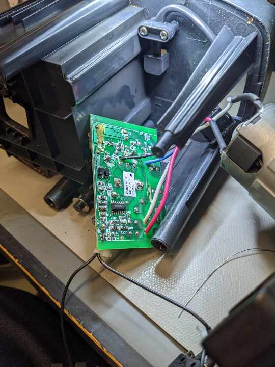
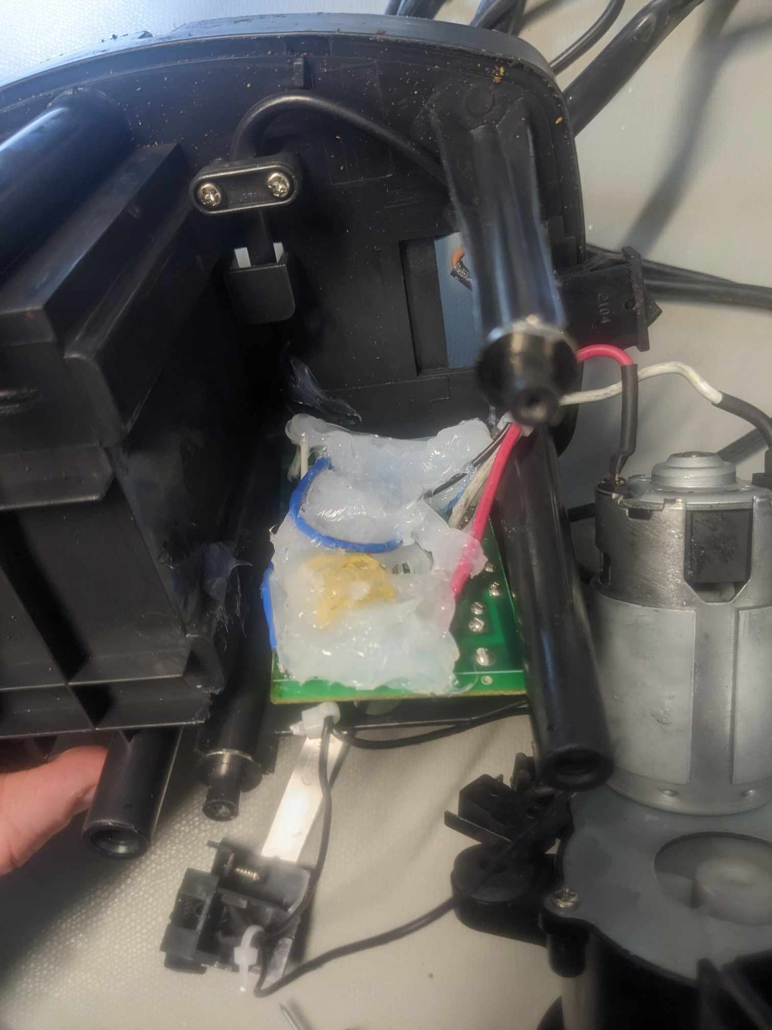

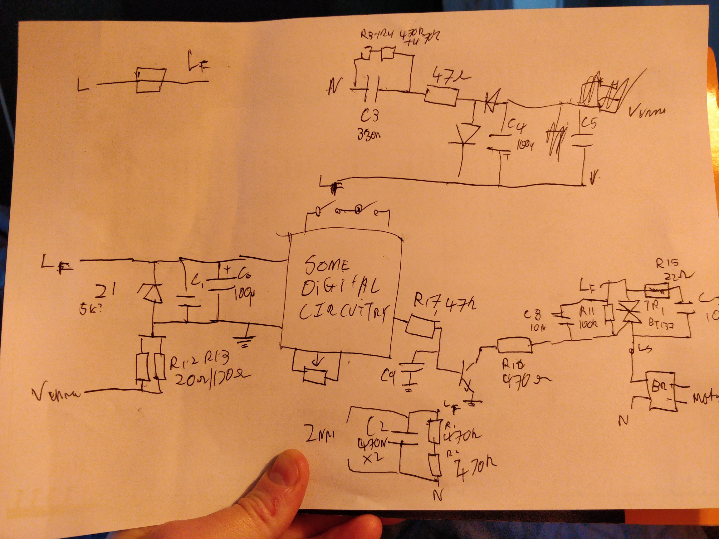
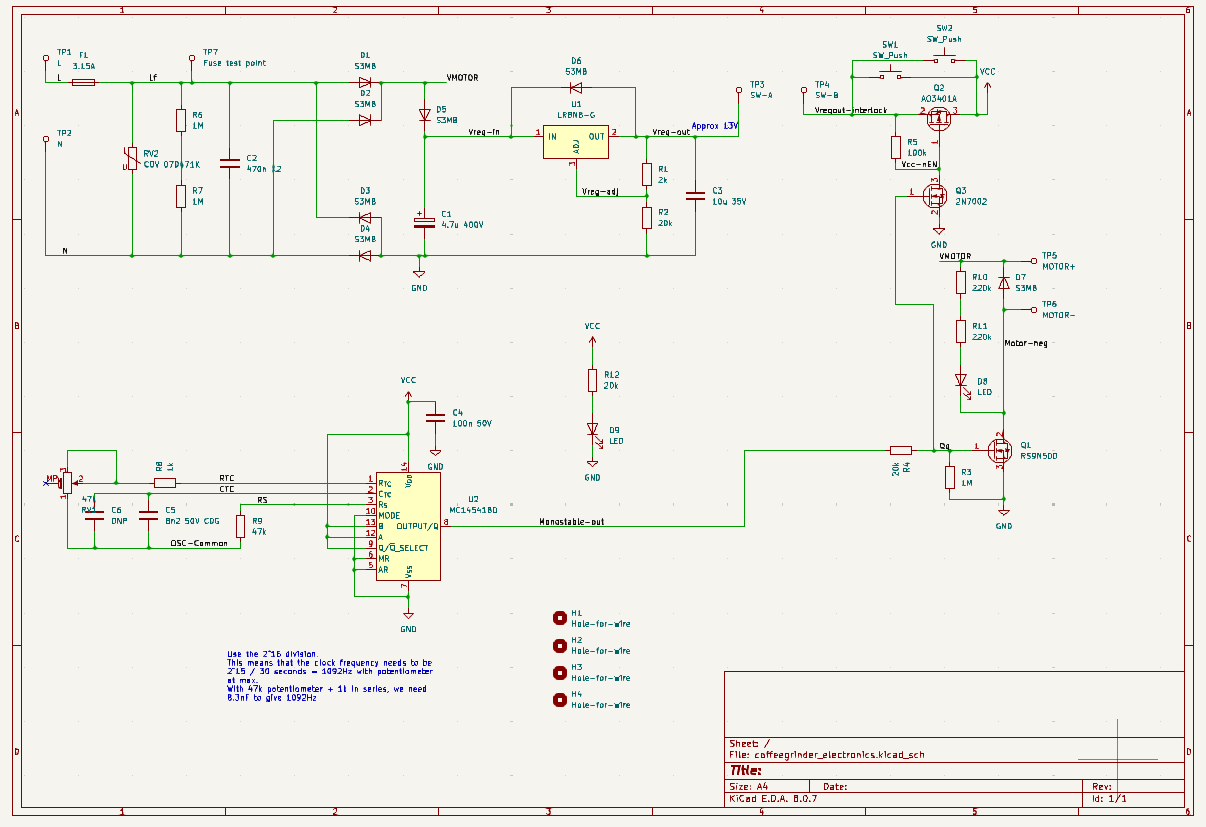
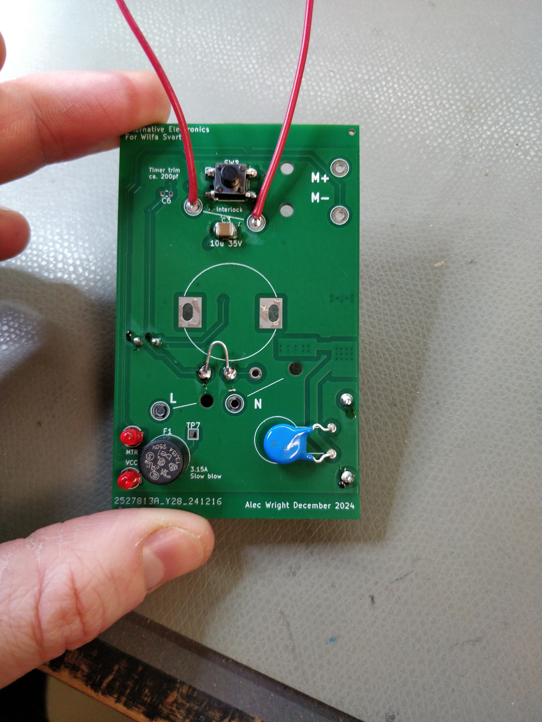
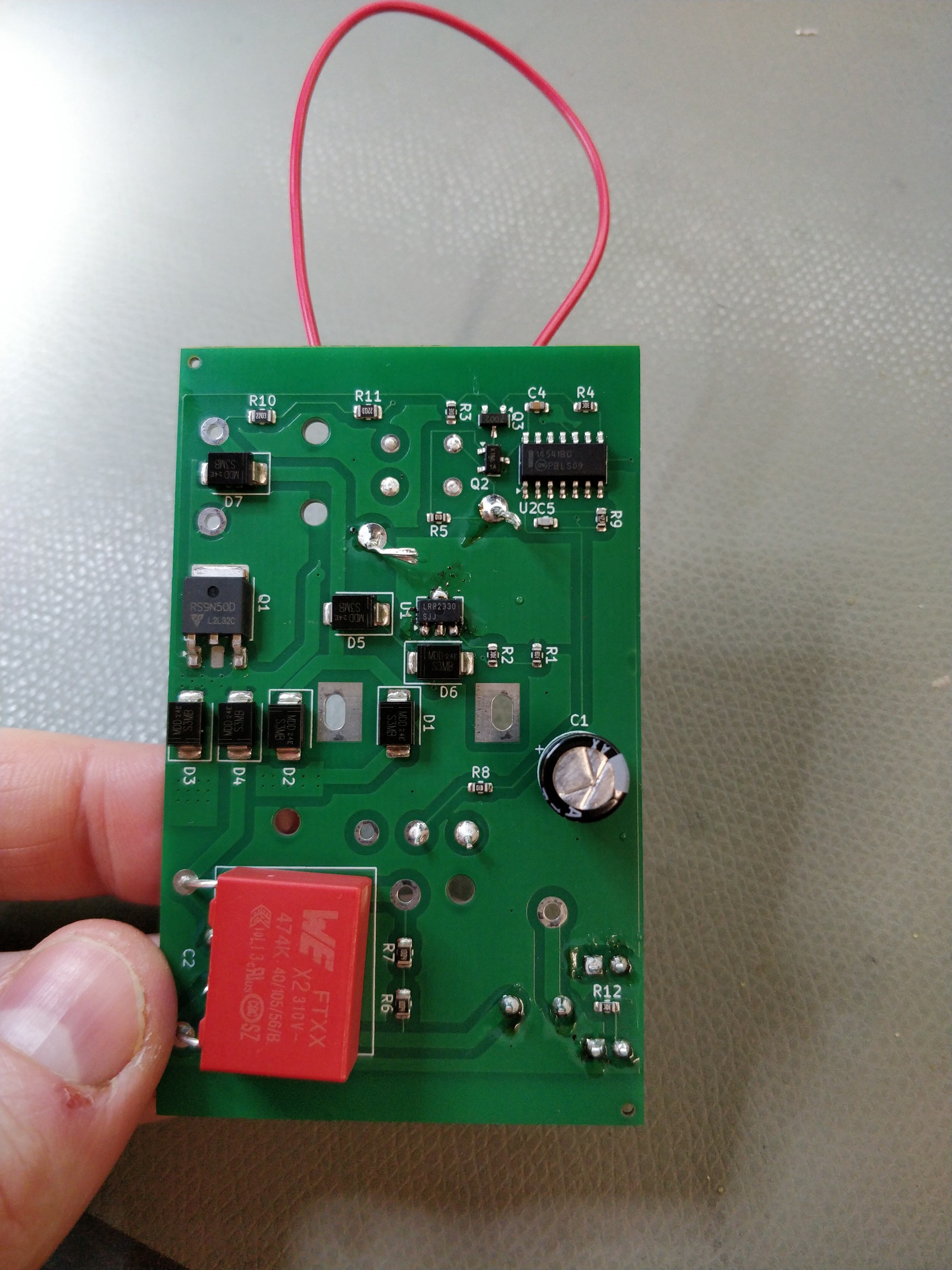


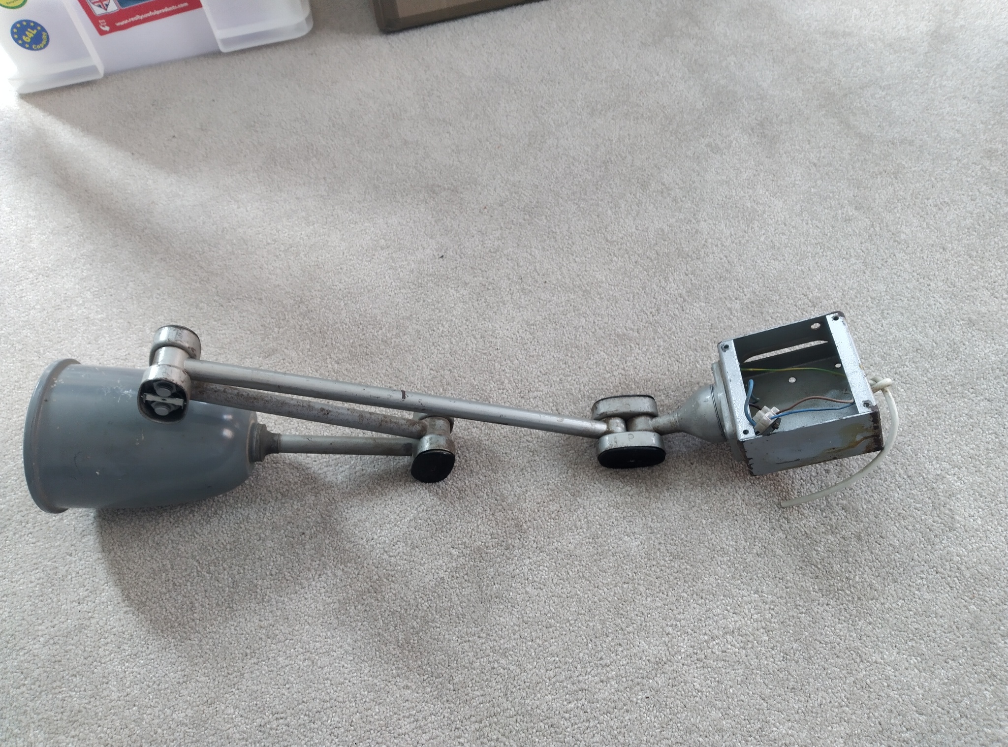
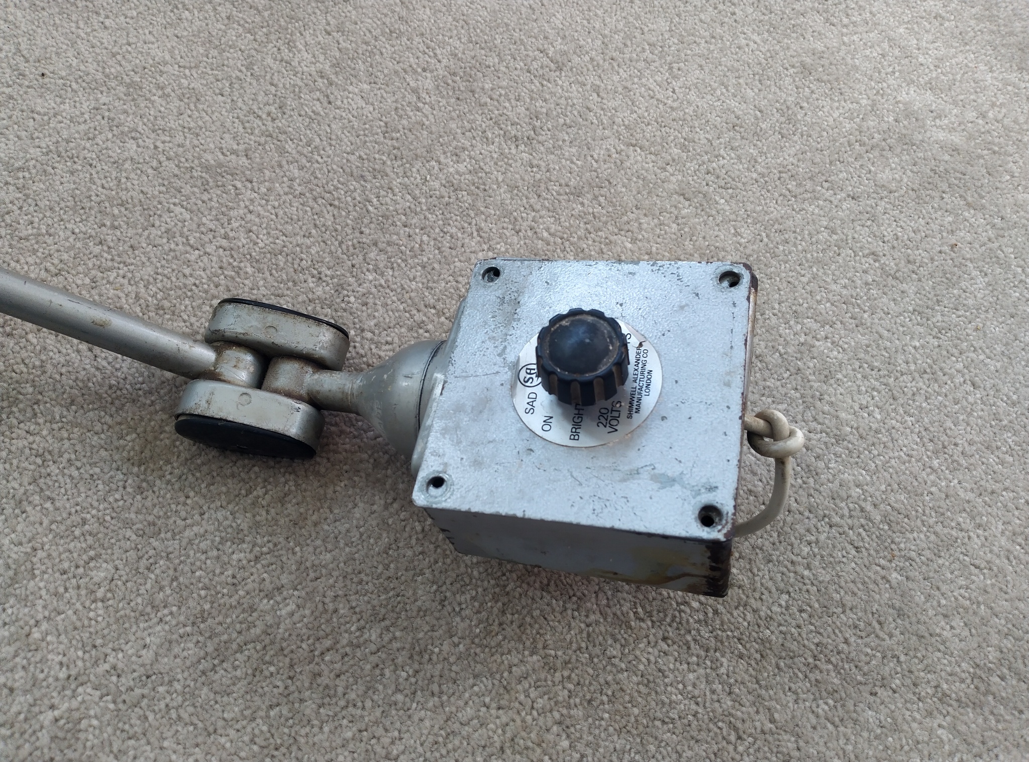
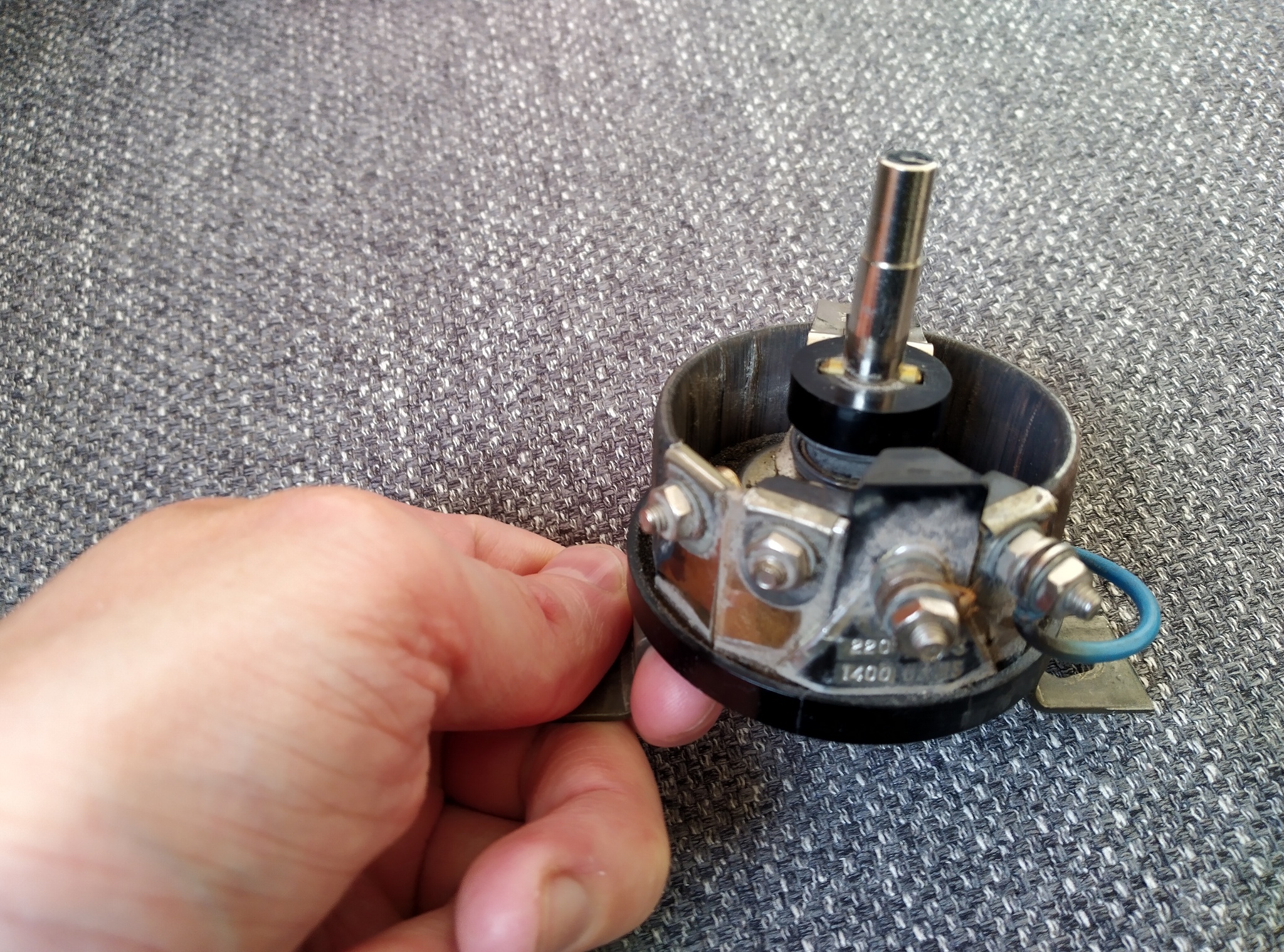

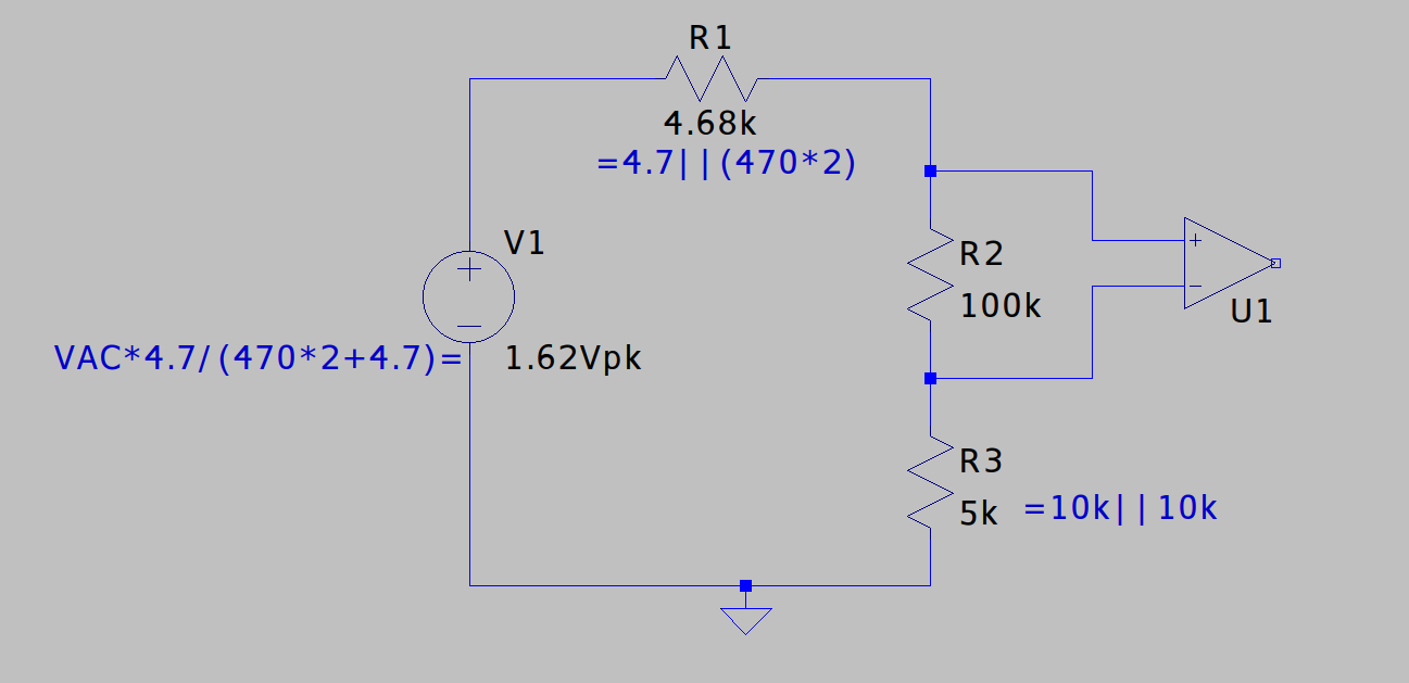
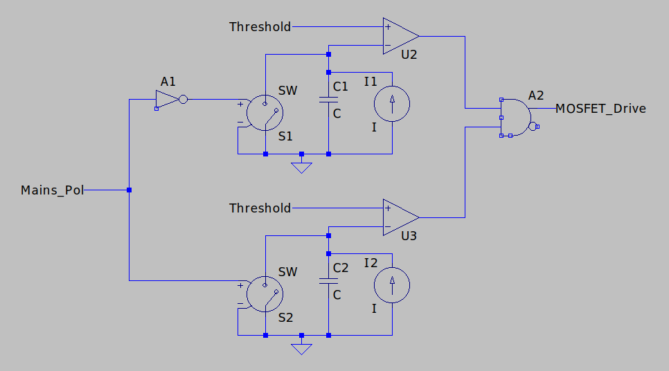
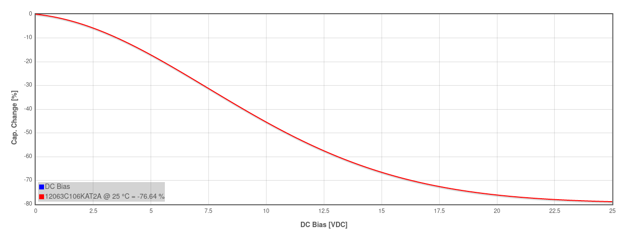


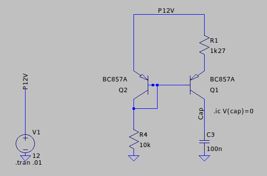
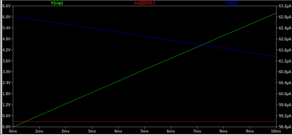
 I_s ( e^{\frac{qV_{be,Q2}}{kT}} -1 )")
}{kT}}")

 e^{-\frac{q R1 I_o}{kT}}")
")
^2\right)}")
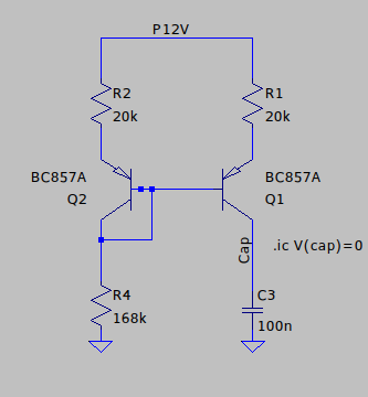
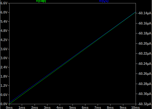

\left( R1\frac{dI_o}{dR_1}+I_o \right)")
}{1-\frac{I_oR_1}{v_t^2}\left(I_oR_1-V_B\right)}")
 , which is the ratio of the voltage across R1 to the thermal voltage, and
  , which is the ratio of Vbe to the thermal voltage. Both will be significantly greater than 1, and their product even more so. Thus we can ignore the 1 in the denominator and so the equation simplifies down to: