This is a followup to my previous post on retrofitting the Kenwood Chef A901 electronics to an A701a. I was quite happy with the result but the implementation was a little hacky. I decided it could be improved by designing a PCB for it.
Schematic Design
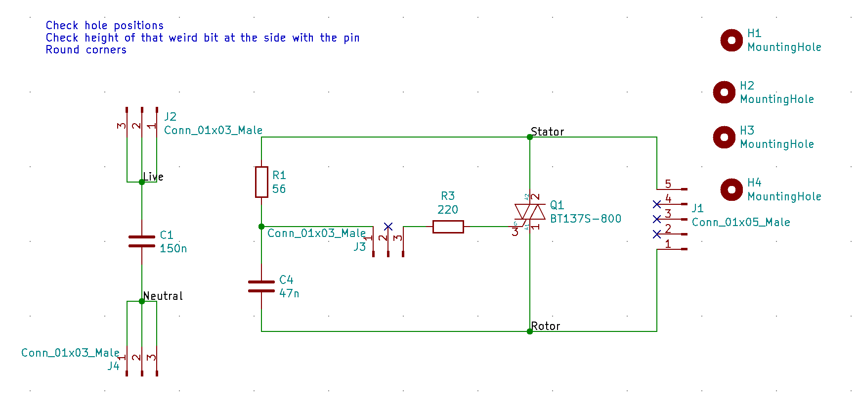
Conveniently, the BT137-800E which I’d chosen previously is available in a DPAK as well as TO220, so there was no need to consider component substitutions. I threw together a schematic in KiCAD:
For the resistors, conventional wisdom seems to be that the 56R should be 1W and the 220R should be 2W. To assess this critically, let’s have a think about what the currents might be. When the TRIAC is switched off, all of the potential will be between the nets labelled Stator and Rotor. When the TRIAC isn’t triggered, the only current path is through R1 and C4. At 50Hz, the 47nF capacitor will have a high impedance and the dissipation in R1 will be less than a milliwatt.
Imagine now that the TRIAC is triggered (the governor switch closes): we have up to 230V*sqrt(2)=325V across (56+220) ohms instantaneously. That’s up to 192W. However, the thyristor is specified to turn on within 2us typical:

This would suggest an average dissipation, split between the two resistors, of 192W*2us*50Hz*2=38mW. In addition, when the thyristor is on, there might be up to 1.65V across the resistors, adding a further 10mW of dissipation. So clearly the rating of the resistors isn’t driven by average power dissipation. Instead, it’ll be driven more by voltage rating, and surge rating. The 56W resistor will see a maximum of 38W and the 220R resistor, 153W. Looking at the surge ratings for a CRCW chip resistor, it looks like sizes 1210 (0.5W) and up might be suitable for the 56 ohm resistor but even the 2512 (1W) is borderline for the 220 ohm:
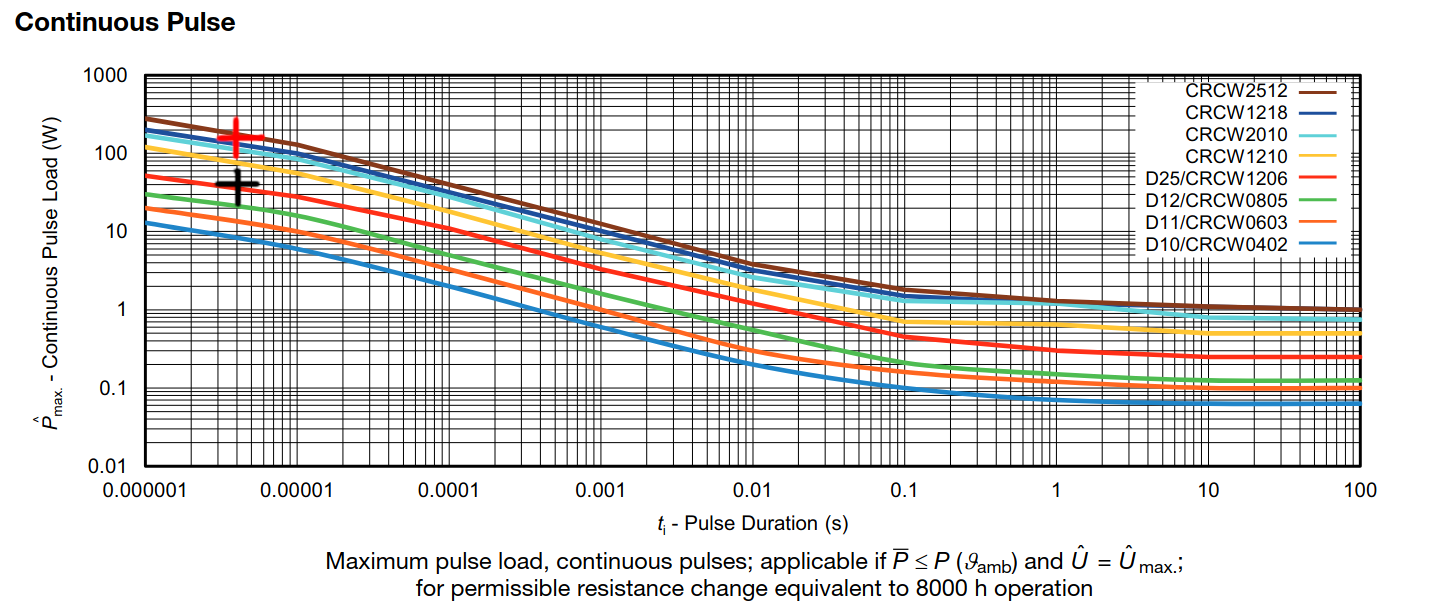
It seems sensible to apply a derating of around ~50% for long term reliability, so I selected a 2512 resistor for the 56 ohms (matching up with the conventional wisdom of using a 1W part!) and I decided that none of these conventional chip resistors would be suitable for the 220 ohm one. Instead I looked at 2W through-hole resistors.
It turns out pulse rating curves for through-hole metal oxide resistors don’t seem to exist. Instead, I found this from a panasonic metal-oxide resistor datasheet, which suggests that the only limitation on pulsed operation is that the average pulse power doesn’t exceed half of the rated continuous power, nor does the peak voltage exceed the pulse limit voltage:

Presumably this is due to the construction of the resistor allowing good instantaneous transfer of heat from the element, and perhaps the less miniaturised construction allows for less hot spots/pinch points. This would seem to suggest that even the smallest (1/2W or 1/4W) metal film resistors would suffice. However, curiously, the datasheet seems to suggest that this model is only valid for periods of over 1 second. I’m not sure why that is – I wonder if it’s a mistake and actually is intended to say T<1s? Otherwise this would suggest I could overload a resistor indefinitely, provided the average power constraint is met! Still, I decided to play it safe and use a 2W resistor, in case there’s something I’ve missed and so that I’m not relying on the pulsed voltage rating (only 2W and up are rated to 350V!).
I selected X-rated caps with a 250VAC rating. The 150nF cap certainly needs to be X-rated as it’s placed across the supply. The 47nF I’m less convinced about: X-rated capacitors are typically used in across-the line applications, but here it seems to essentially be decoupling the TRIAC gate. The other reason I’m aware of for choosing an X-rated capacitor is the self-healing effect following dielectric breakdown. That link suggests that around 100mJ is required to heal, which could be provided through the 56 ohm resistor in around 200us. Although by that point the resistor would already be fried, so you have to wonder if the X-rated capacitor gives any advantage vs a much more compact MLCC (eg a 47nF 500V 1206 X7R). Indeed, a common failure of the A901 is of the 56 ohm resistor, presumably for exactly this reason. Still, I erred on the side of caution and copied what was done on the A901.
PCB Layout
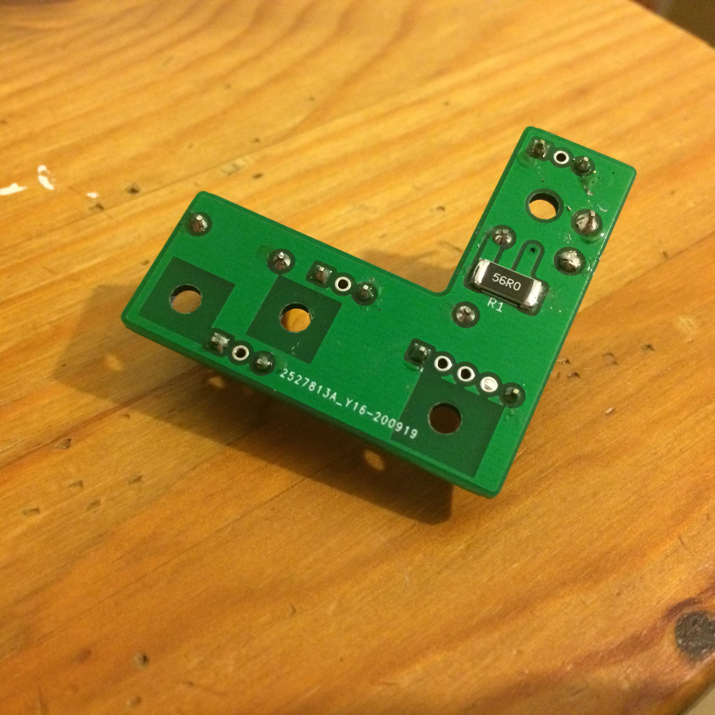
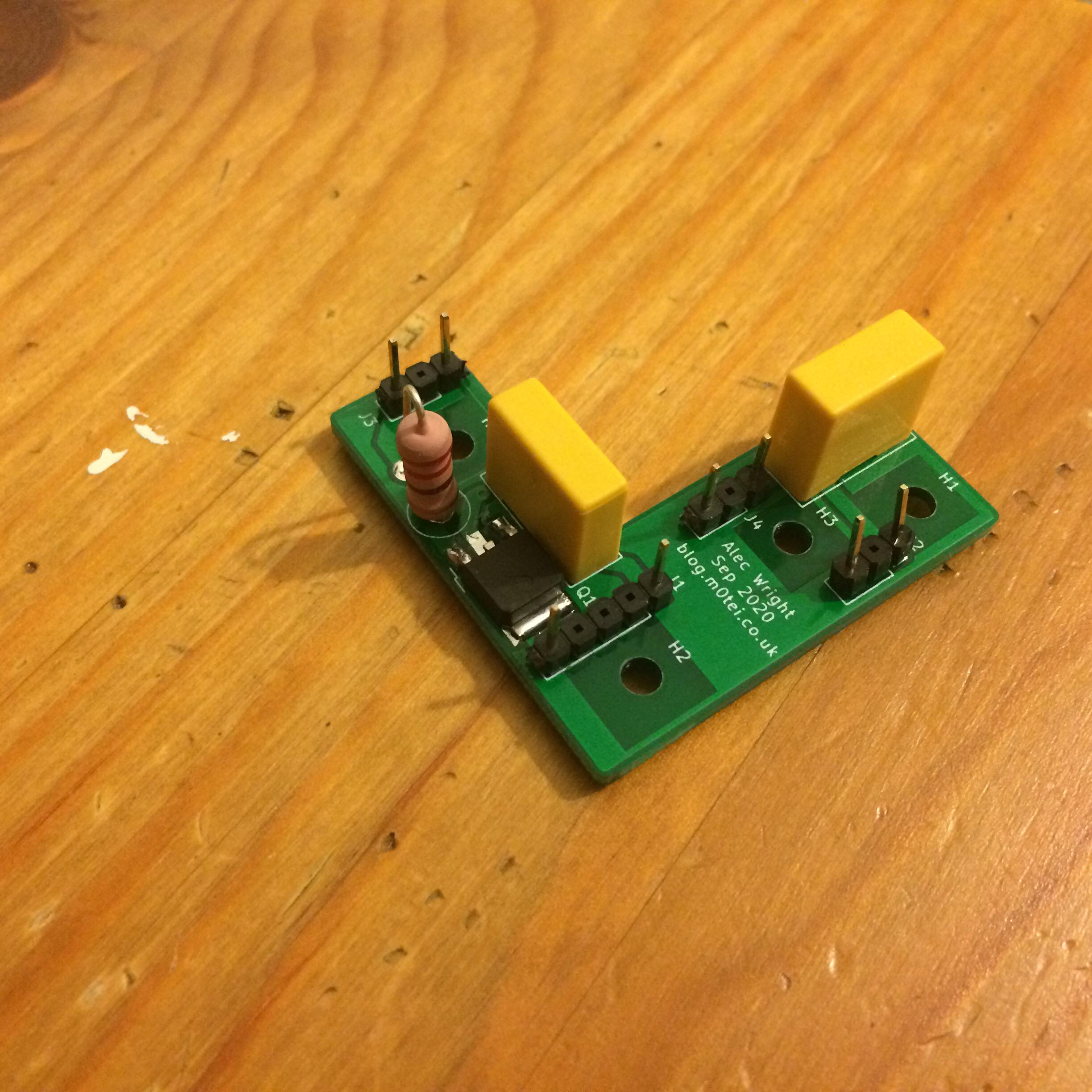
Here’s the laid out PCB. I measured up the contact bar and designed the PCB around the size of that and the holes available for mounting. I had to drill (if I recall correctly) one of the holes out to 3.2mm, while the others were already the right size. Rather embarrassingly, I forgot to apply a copper keepout around one of the mounting holes on the bottom! Luckily though, I ended up using plastic mounting pillars anyway, so this didn’t really matter. In hindsight, I should probably have increased track-to-plane clearances or even removed the plane entirely (it serves no purpose other than habit and isn’t connected to a net!).

Gearbox Hell
You might wonder why the PCB has a date of September 2020 on it and I’m posting this in July 2021. It’s actually nothing to do with the circuit – that worked perfectly. It’s the gearbox where the problems started.
I decided to replace the grease in the gearbox, with it being around 50-60 years old. This ended up with me getting quite out of my depth with lubricant science!

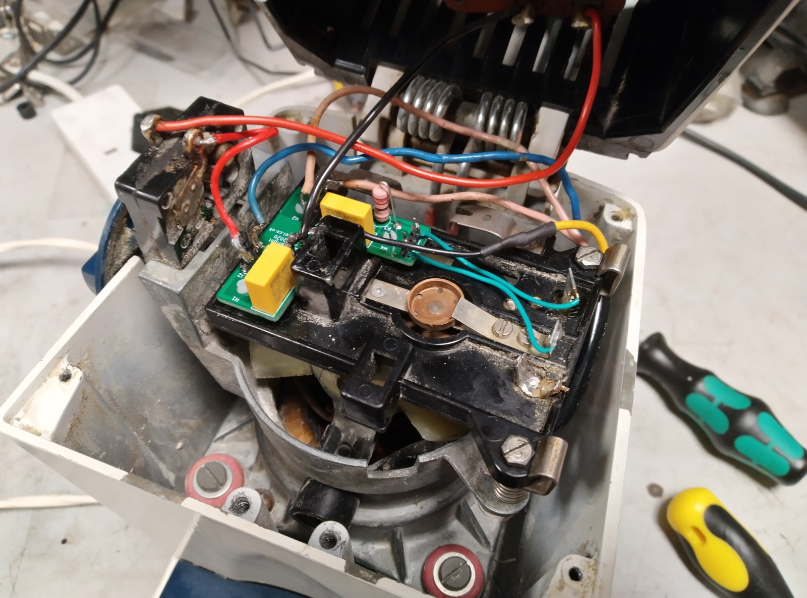
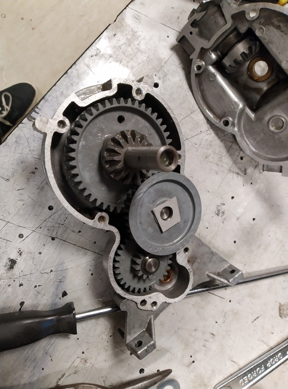
Getting into the gearbox in the first place presents a bit of a challenge. Like the cassette on a bike, the nut on the dog clutch tightens during use and freewheels when you try to loosen it. To undo it, you need to jam up the mechanism to give you something to push against. I managed this in a vice with a screwdriver jammed in the planetary gearbox.
One thing I read about lubricants is that mixing different greases is fraught with danger. Unless you’re very careful you risk creating an inhomogeneous mixture, potentially with unexpected properties. From this, I reasoned that I needed to clean the old grease off pretty thoroughly first.
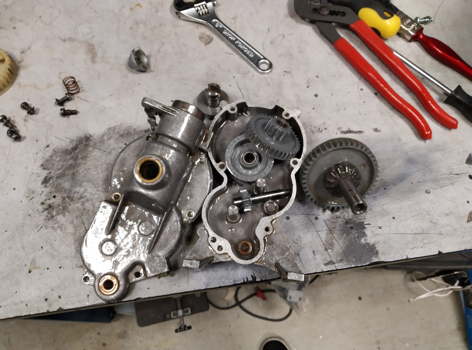
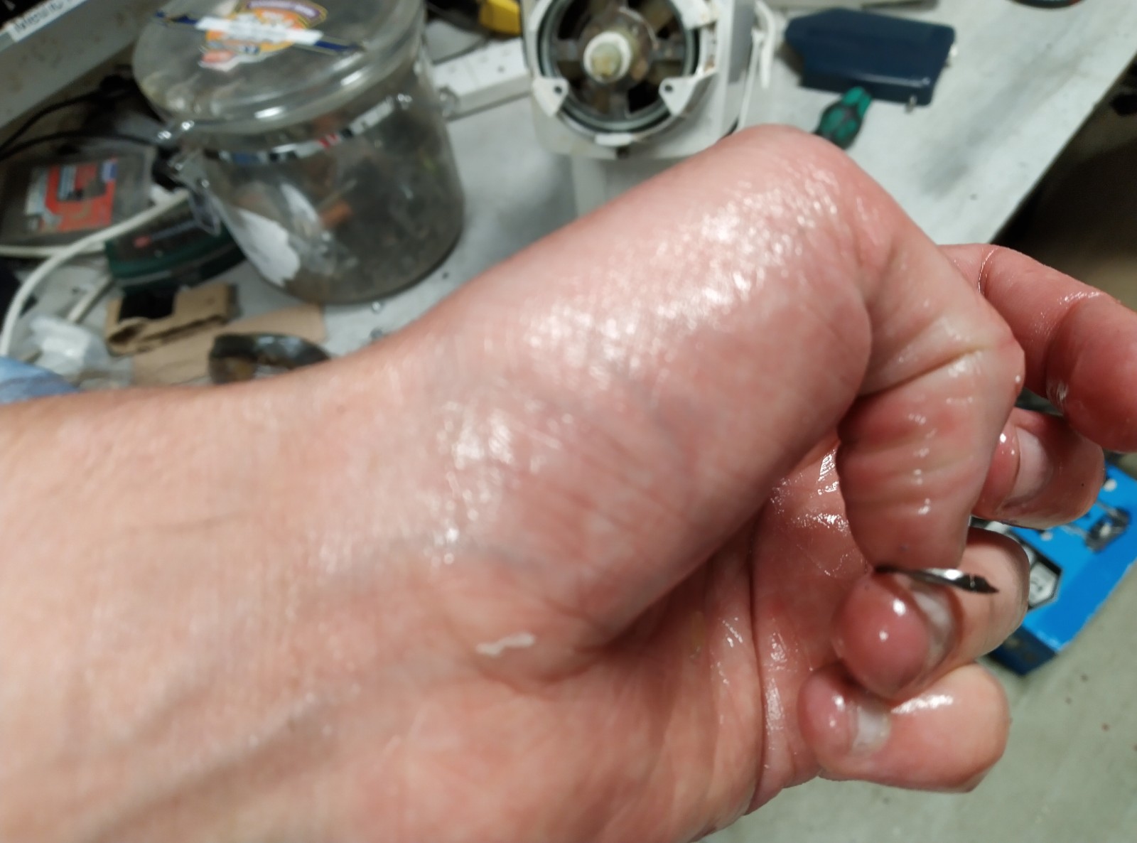
I removed the grease with tissue initially, and with white spirit and a brush to finish. Here are the parts mostly (but not completely) clean.
This is where it went wrong: I chose comma multipurpose grease simply because it was available easily and cheaply. I put it all back together with some silicone sealant around the outside.
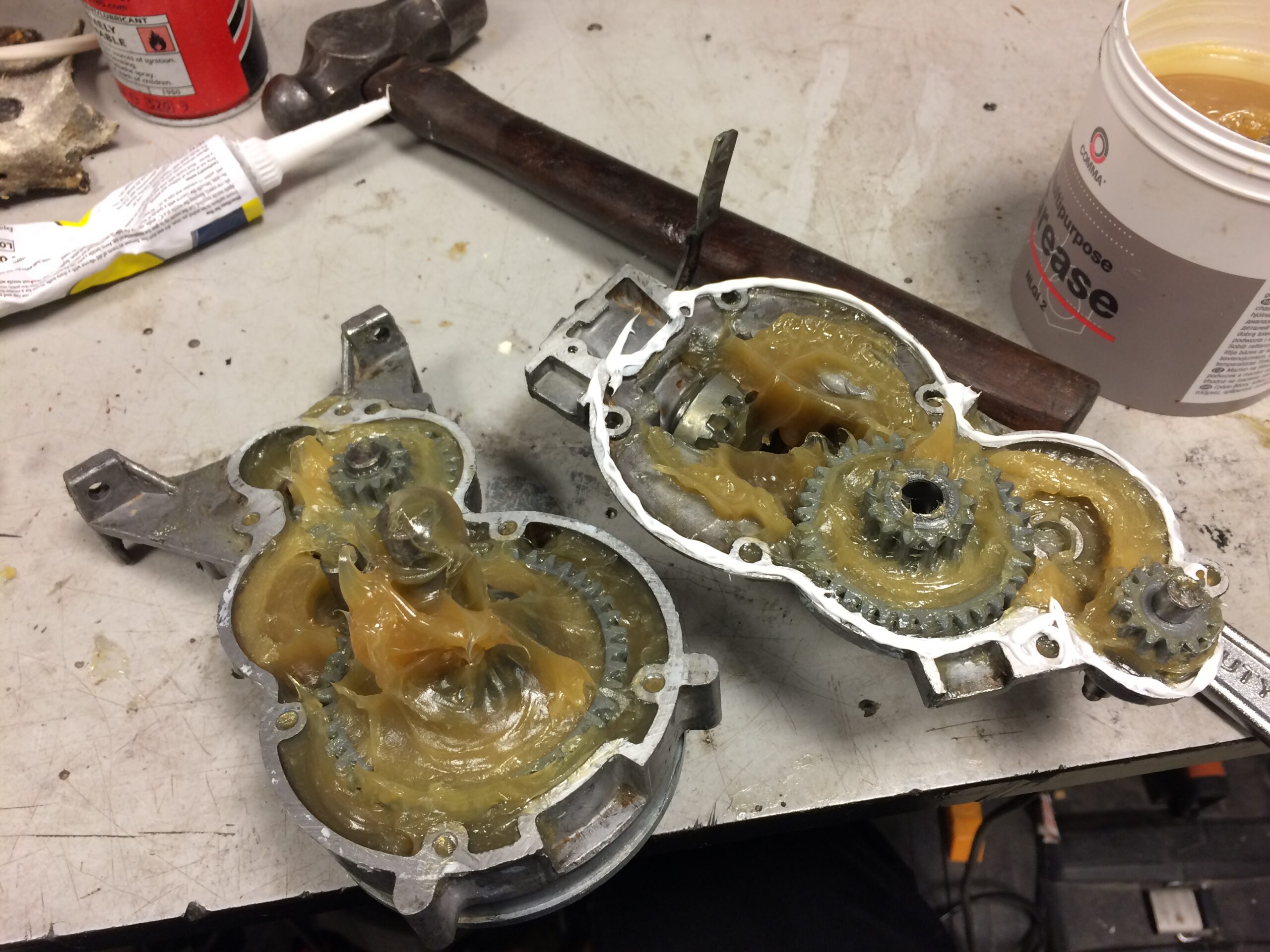
When I reinstalled the gearbox, I found that it got quite hot while working and the mixer’s speed was limited to about 6 of the 8 arbitrary units marked on the speed knob (I didn’t think to actually measure the RPM – easy to do with just a stopwatch!). It was at this point that I realised I’d used too thick a grease and the project stalled for months as I couldn’t face opening and cleaning the gearbox again.
It turns out, the thickness of greases are measured on a scale referred to as NLGI consistency. While a simple oil is measured by its viscosity against temperature, greases are non-newtonian so it doesn’t make sense to define viscosity as a function of temperature alone. Instead, the NLGI consistency gives a more meaningful way to classify the response of a grease to shear forces.
The grease I’d selected had an NLGI consistency of 2. Looking through the service manual for the mixer, the specified grease is “Shell L.G.P.1”. While I couldn’t find any information on this (presumably discontinued) grease, the 1 at the end suggests an NLGI consistency of 1: in shopping for greases, I found the common nomenclature seems to be some kind of name and/or acronym, followed by the NLGI consistency.
It turns out the market mostly comprises NLGI 2 greases. A lot of grease types seem to be only made in this one consistency, and the few which are available in NLGI 1 seem to be hard to get hold of in small quantities. I did eventually find one suitable grease though: Castrol Spheerol EPL 1, of which I managed to pick up a single tube online.
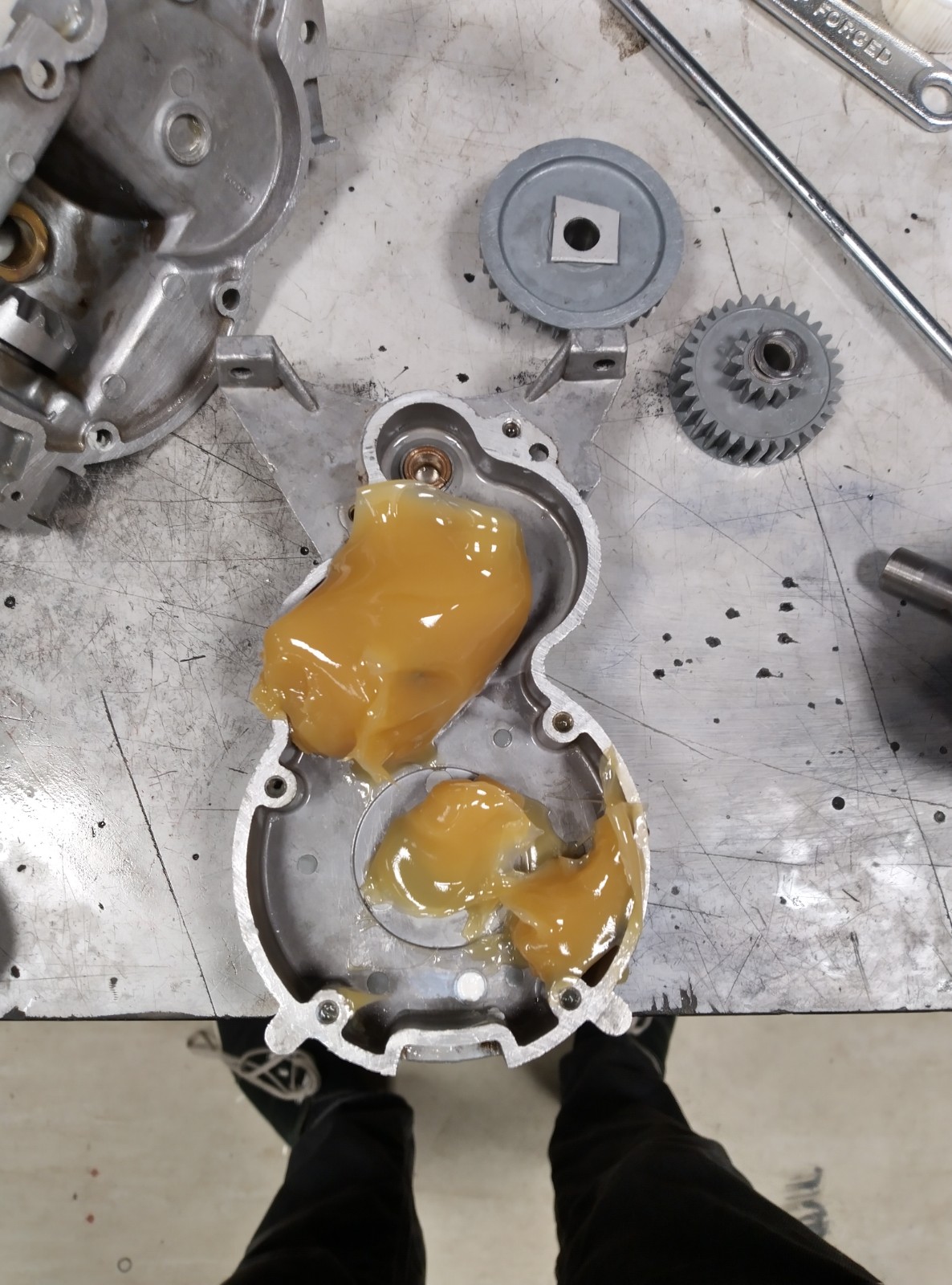
Eventually I summoned up the motivation to strip down and clean the gearbox again. Apparently this is the only photo I took where you can see the new grease, but you can tell from the smoother surface that this is, indeed, thinner.
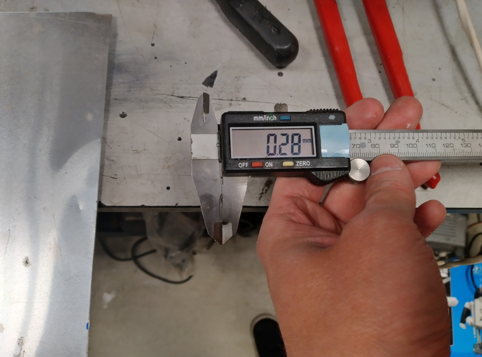
One snag was that I found one of the washers had gotten mangled. When I tried to bend it back into shape, it snapped. It was much thinner than a conventional washer (I measured it at 0.3mm thickness) and seemed to have an imperial inner diameter of 6.35mm – and since it needed to be a tight fit around the shaft, the next size up of metric washer wouldn’t be suitable. With no replacement lying around, I decided to bodge something.
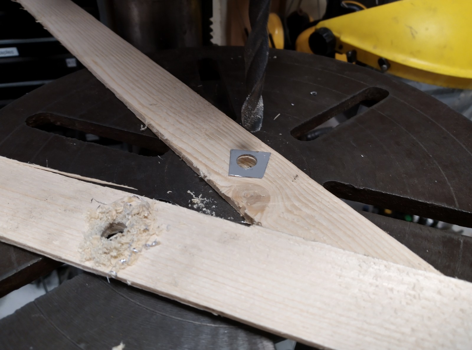
I picked a piece of sheet metal from the scrap pile with a similar thickness and cut it down to fit within one of the gears. With such thin metal, I needed to clamp it between two pieces of wood as I drilled the 6.5mm hole, to avoid burring and bending of the metal. This seemed to work, and the gearbox moves freely.
Once I put everything back together, it went a bit faster than before but still slower than it should be: about 120rpm, when the service manual says that full speed should be 180-200rpm. I suspect the grease is still too thick: the original grease I took out of the thing still seemed thinner than the second lot I put in. If I was doing this again, I’d consider using NLGI 0 grease (the same Castrol Spheerol is also available in NLGI 0) but I think now I’ve run out of motivation to pursue this any more and I’ll accept that this is a mixer best suited to kneading dough rather than making meringues.
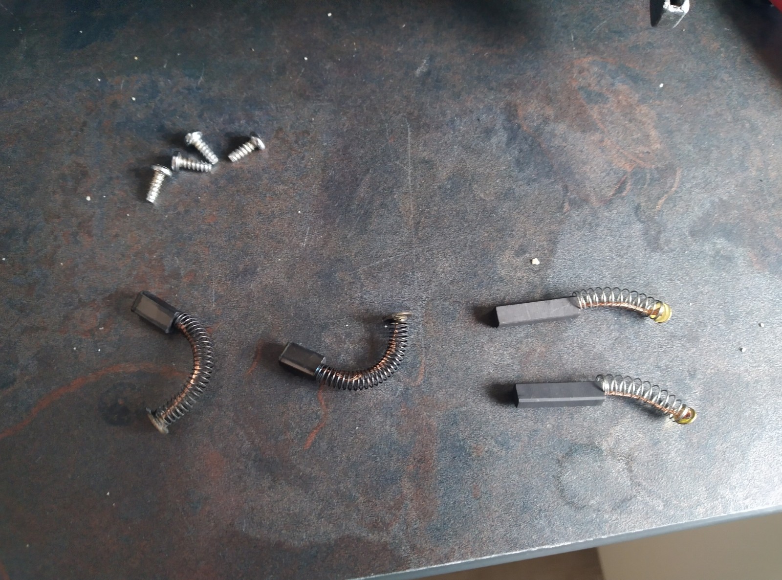
I did think that the speed might be due to friction in the motor: it didn’t seem to speed up much without the dog clutch engaged. I took the motor out and squirted a bit of oil into the bearings which seemed to increase the no-load speed, but it still slowed down to around 120rpm with the dog clutch engaged. At the same time I checked the brushes and found that they were quite worn. Since I had some replacements lying around, I switched them in.
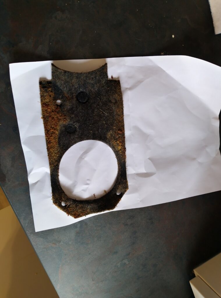
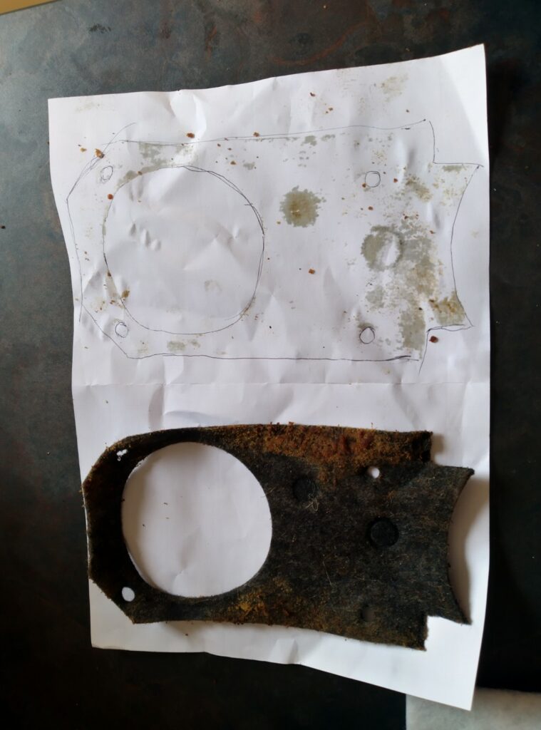
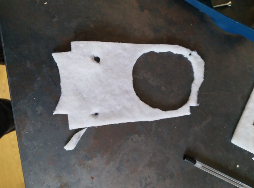
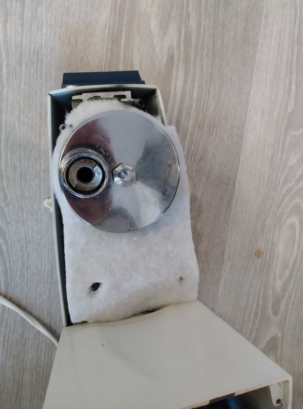
After replacing the rubber feet, the final thing to do was replace the felt. I had a piece of some kind of fibrous material lying around, I think a piece of cooker hood filter. It seemed to be quite good at soaking up grease, so I figured this would be suitable. I traced around the original greasy felt and used that as a guide to cut out a replacement.
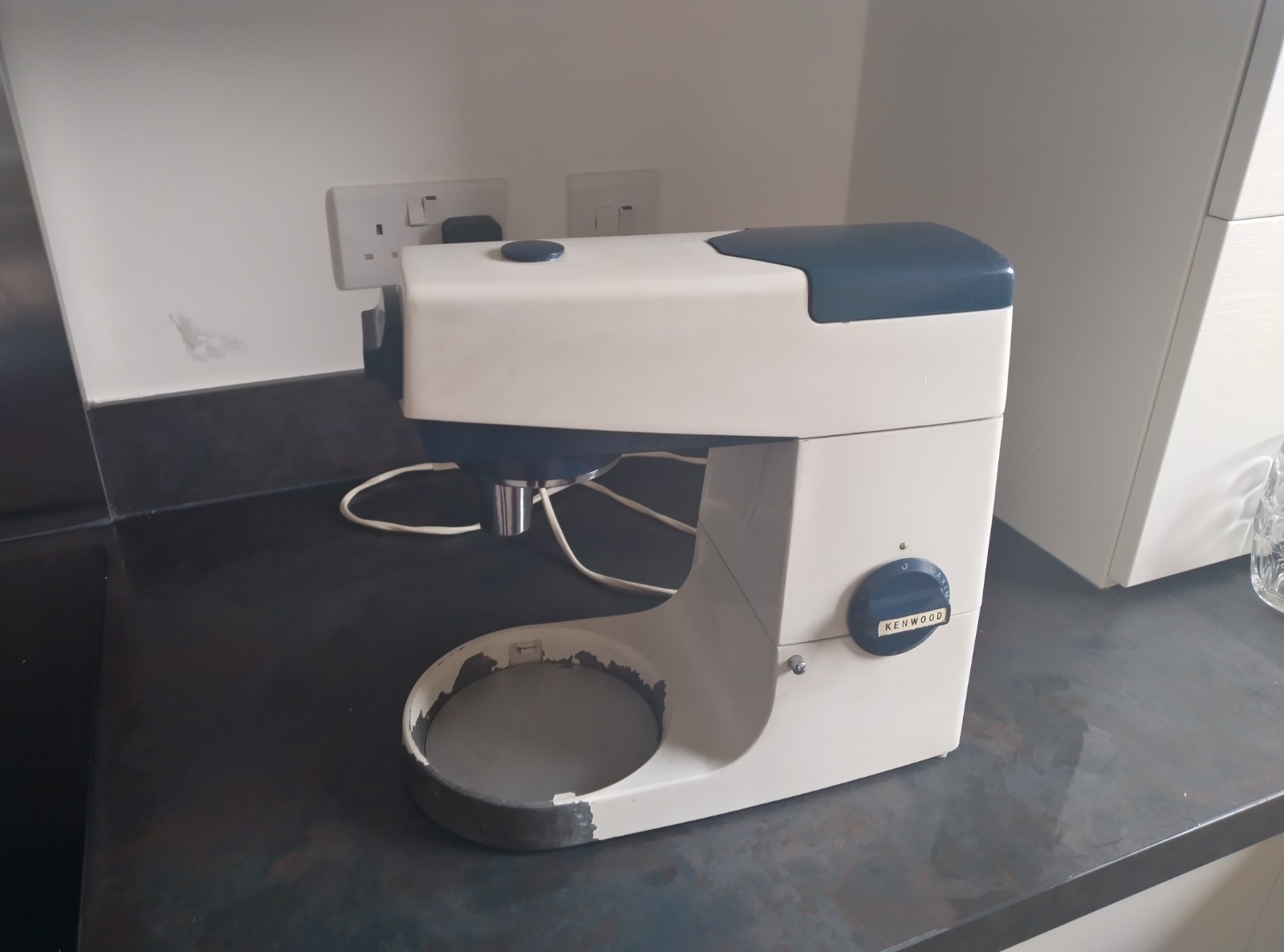
Here’s the finished thing. It’s been a learning experience! KiCAD project is available here.
4 replies on “Kenwood Chef A701a Electronic Speed Controller Retrofit – Part 2”
This is very interesting; it would be great if you could add a video of the updated machine in operation. The circuit board in particular looks like a good fit. The technical explanation goes above my head, but it’s the 56 ohm resistor which usually fails and these are up-rated to 2 or 3 Watts in all of the spares kits for sale on eBay. The 220 ohm resistor rarely (if ever) fails. I’d be interested to know if there is any benefit in a particular type of 56 ohm resistor in this application – i.e. carbon, metal film or wirewound.
This is the second 701a I’m repairing for family with a motor problem. Following your detailed and thorough work on the speed control circuit and board, have you a kit on the market? If so where?
Sorry for taking a while to approve your comment and reply! I’m afraid there’s no kit! I’ve included the gerber files in the post though, so if you want to make your own you can use those!
As for the parts, I used the following parts from LCSC but you should be able to make some substitutions:
C172286
C121647
C242700
C390052
C390057
C59911
Interesting project, might try it one day. What is the pc board, was it one you cut up or did you etch one specifically? I use lithium based grease in the gearbox and food safe in the planetary. Well done, someone in NZ who repairs Kenwoods was asking if there is an aftermarket speed controller available for the 701 so I will share this.